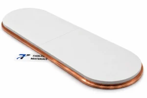
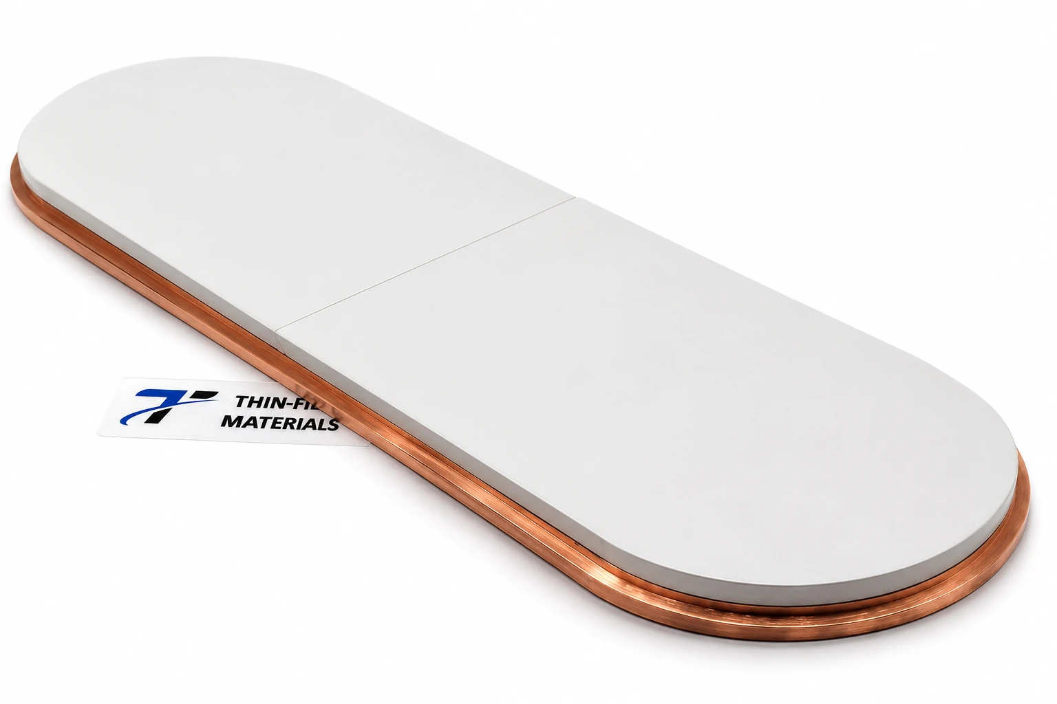
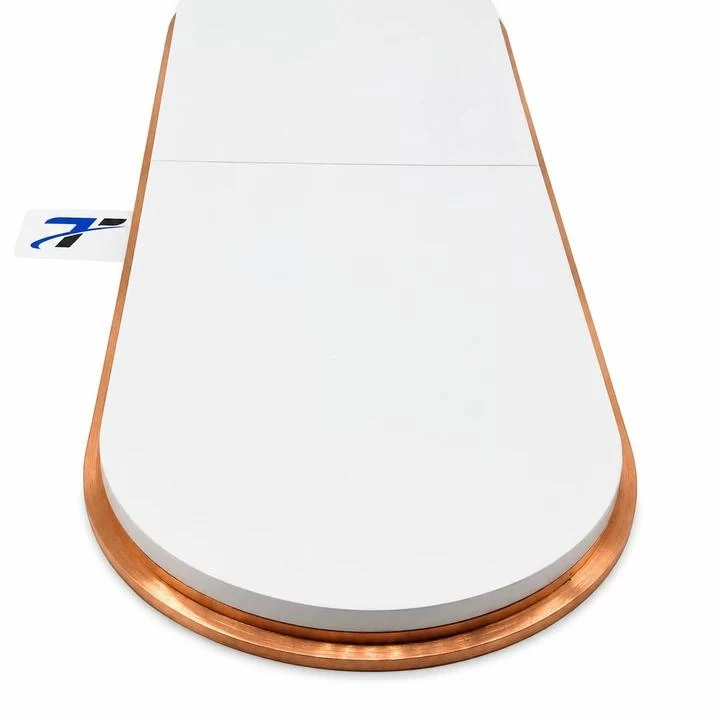
TFM manufactured and shipped a segmented lithium phosphate (Li3PO4) sputtering target with a specified size of 114 × 356 × 6 mm. Two ceramic pieces form one target assembly, with a 45° beveled overlap joint and elastomer bonding to a common copper backing plate.
TFM coordinated the ceramic outline, seam position and working-face alignment with the copper plate. The case follows that assembly work and the drawing details needed for a similar order. Installation and film qualification were outside the reported project scope.
Project configuration
| Item | Configuration in this project |
|---|---|
| Target material | Lithium phosphate, Li3PO4 |
| Specified size | 114 × 356 × 6 mm, as stated for the project |
| Ceramic construction | Two segments forming one rounded-end target |
| Joint | 45° beveled overlap |
| Backing plate | Copper |
| Bonding | Elastomer bonding |
| Delivery unit | One complete bonded assembly containing two ceramic pieces |
| Project status | Manufactured and shipped |
For a replacement, use the approved drawing to distinguish ceramic thickness, backing-plate thickness, bond-line allowance and complete installed height. The size callout alone does not define all four. Material enquiries should reference the Li3PO4 sputtering target product page; purity and inspection requirements belong in the individual order.
Handling an elongated ceramic target
At 356 mm long, the target required support during processing, transfer and final positioning. Concentrated loads can chip ceramic edges, while unsupported spans introduce bending stress. A one-piece target must be handled at its full length throughout those operations.
The two-piece design allowed each section to be processed and positioned separately. At assembly, the segments had to meet at the intended seam while preserving the outline and relative working-face height. The narrow beveled edges needed attention during handling.
For procurement, that means the individual tile drawings and the assembly drawing should agree. A tile that meets its own dimensions does not establish the fit of the complete target. The sputtering target drawing checklist covers the geometry and revision information to include in an RFQ.
What the 45° beveled joint changes
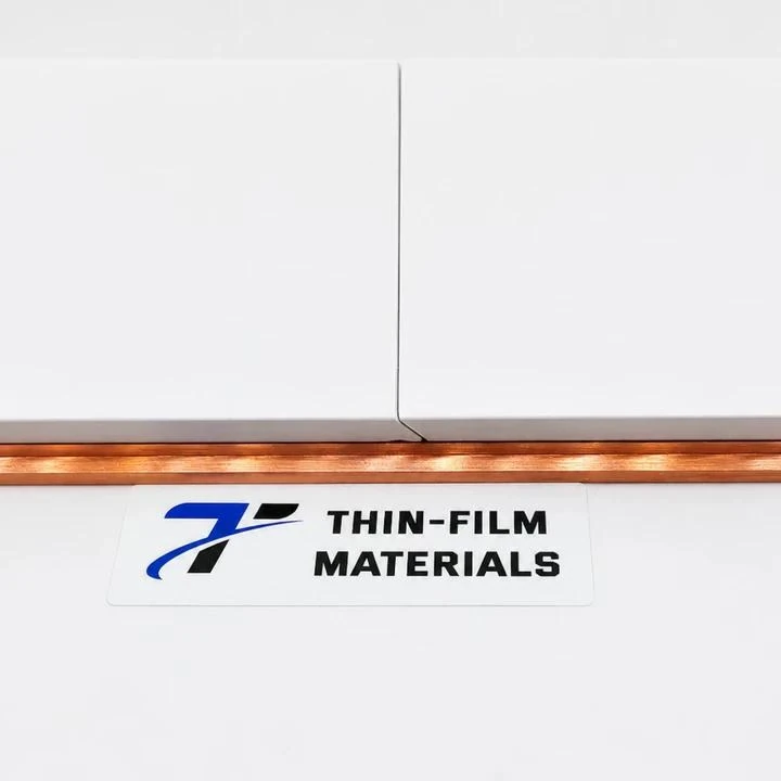
In a square butt joint, the mating faces run perpendicular to the working surface. Here, the two adjoining edges form an inclined overlap through the ceramic thickness. The close-up shows the surface seam and its transition at the near edge.
| Construction | Interface | Drawing and manufacturing consideration |
|---|---|---|
| Single piece | No segment joint | Process and support the full ceramic length. |
| Segmented butt joint | Square-ended mating faces | Specify joint clearance and relative face height. |
| Beveled overlap | Inclined mating faces | Coordinate the bevel, clearance, seam position and segment alignment. |
Beveled tile interfaces also appear in published target designs, including US20060266639A1. That reference provides geometric context; it does not establish the performance of this Li3PO4 assembly or identify the process used to manufacture it.
The joint layout must suit the cathode and expected erosion region. A 45° interface alone does not demonstrate better film uniformity, longer target life or freedom from arcing. Joint clearance, segment thickness and working-face alignment still need to be specified and checked for the intended assembly.
Copper backing and elastomer bonding
Both ceramics were elastomer-bonded to the same copper plate. The plate supports the target and forms part of the mechanical and thermal connection to the sputtering source. Heat transfer also depends on the bond layer, rear contact and cathode cooling arrangement.
Elastomer bonding provides a compliant interface between ceramic and metal. As general industry context, Kurt J. Lesker’s elastomer-bonding guidance discusses fragile targets and lists lithium orthophosphate among the materials considered for this approach. Its formulation-specific ratings are not specifications for this TFM project.
On a new order, agree the bonding system and its operating limits with the assembly requirements. Review joint clearance, bond-line allowance and installed height together. Conditioning and power ramping must follow the equipment requirements and the selected bonding system. TFM’s target bonding and backing-plate service is the enquiry route for discussing that scope.
Finished assembly and scope of the result
TFM completed manufacture and shipped one bonded assembly containing two ceramic pieces. The project images show the rounded outline, surface seam and backing perimeter.
Dimensional acceptance depends on the approved drawing and inspection records. The images do not establish purity, density, bond integrity or deposition performance. Installation, sputtering trials and film qualification remain separate from the manufacturing result described here.
Specify a similar Li3PO4 assembly
Send the target and backing-plate drawings together, with their revision numbers. For a segmented design, mark the section count, seam location and joint geometry. Include mounting features, the permitted installed height and any customer-supplied parts. Each new configuration needs a manufacturing review.
| RFQ item | Information to provide |
|---|---|
| Material | Composition, required purity and the basis for any acceptance requirement. |
| Ceramic geometry | Outline, length, width, thickness, tolerances and drawing revision. |
| Segment interface | Section count, seam position, bevel details, clearance and relative face-height requirement. |
| Backing and bonding | Plate drawing, mounting features, bond preference and complete installed-height allowance. |
| Equipment and inspection | Cathode model or assembly drawing, operating context, required inspection scope and documentation. |
| Quantity | Number of complete bonded assemblies; identify separate replacement segments explicitly. |
For plate-material questions, the backing-plate selection guide explains the factors to review. Request a custom Li3PO4 assembly quotation through the product page’s Get A Quote form and attach the drawings you are permitted to share.
Questions about this configuration
Can a Li3PO4 target use more than one ceramic segment?
Yes. This project used two sections on one backing plate. A different size or segment layout requires review of the assembly drawing, joint position and cathode requirements.
Does a beveled joint guarantee better sputtering performance?
No. It defines the inclined interface between segments. Film uniformity, erosion behavior and usable life need evaluation under the intended process conditions.
What drawings are needed for a replacement target?
Provide the ceramic and backing-plate geometry, segment layout, joint detail, mounting features and permitted installed height. Include drawing revisions and the cathode or existing assembly reference.
Does a quantity of one mean one tile or one assembled target?
In this case, it means one bonded assembly containing two ceramic pieces. State the delivery unit in the RFQ; a request for loose replacement segments is a different supply scope.