
Sputtering Target Bonding & Backing Plate Services
TFM provides sputtering target bonding and backing plate services for metal, alloy, ceramic, oxide, semiconductor, and custom sputtering targets. We support indium bonding, elastomer bonding, OFHC copper backing plates, OEM-source replacement plates, and drawing-based bonded target assemblies.
Supply Summary: Indium bonding | Elastomer bonding | OFHC copper backing plates | OEM replacement plates | Customer-supplied plate review | Drawing-based assemblies
Our Bonding & Backing Plate Services
A bonded sputtering target assembly must be reviewed as a complete system. The target material, bonding layer, backing plate, cathode interface, cooling path, and operating conditions all affect assembly reliability.
TFM supports sputtering target bonding, backing plate machining, OEM-source replacement plates, customer-supplied backing plate review, and drawing-based bonded target assemblies according to project requirements.
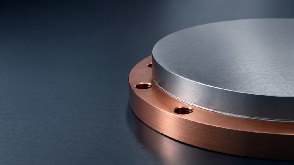
Indium Target Bonding Service
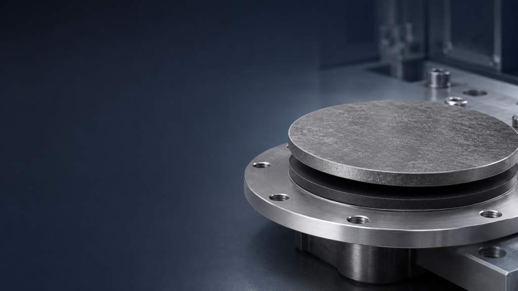
Elastomeric Target Bonding Service
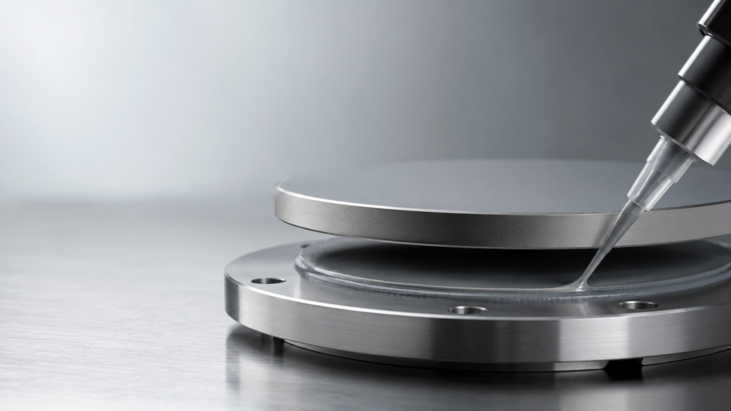
Silver Epoxy / Thermal Epoxy Bonding
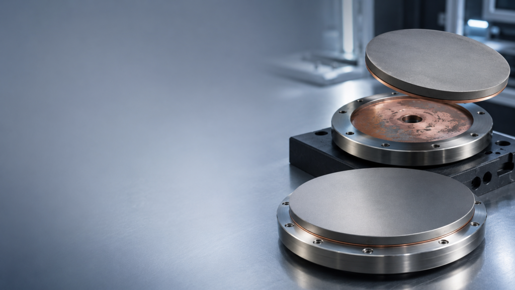
Target Debonding & Rebonding Service
Backing Plate Cleaning & Reuse Review
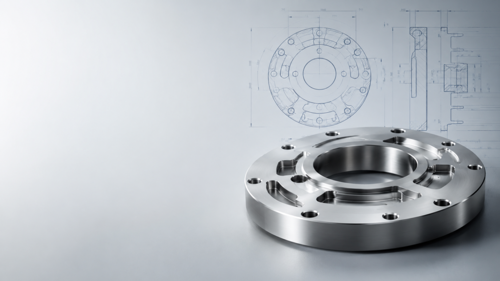
OFHC Copper & Custom Metal Backing Plates
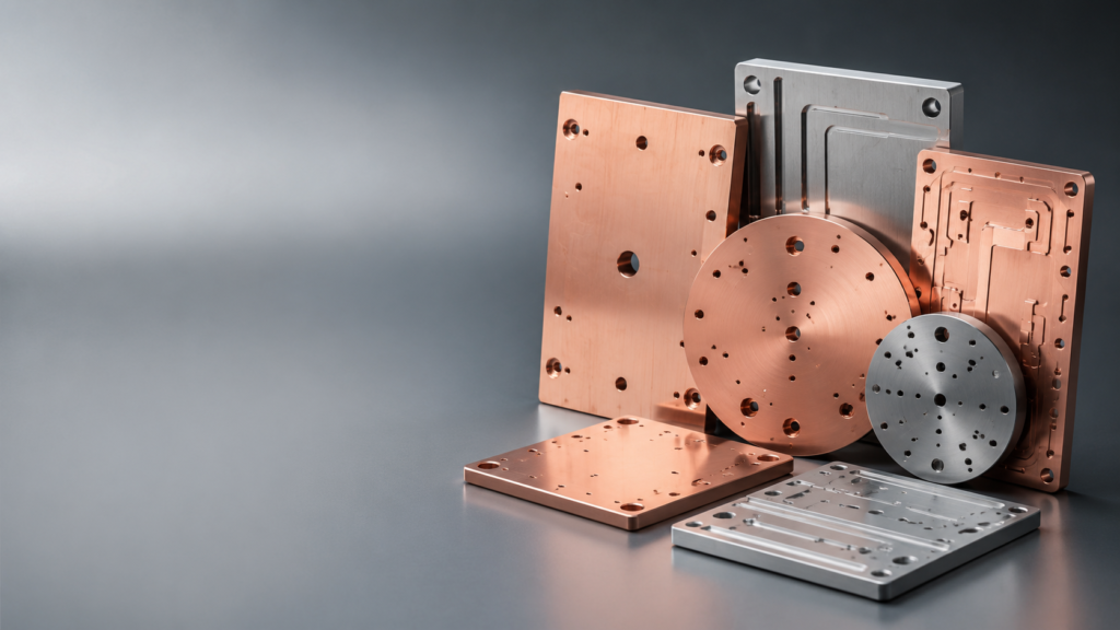
Composite / Low-CTE / Water-Cooled Backing Plates
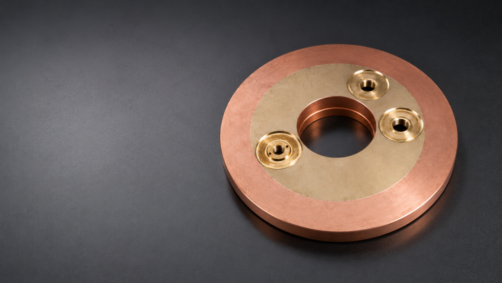
OEM Replacement & Drawing-Based Backing Plates
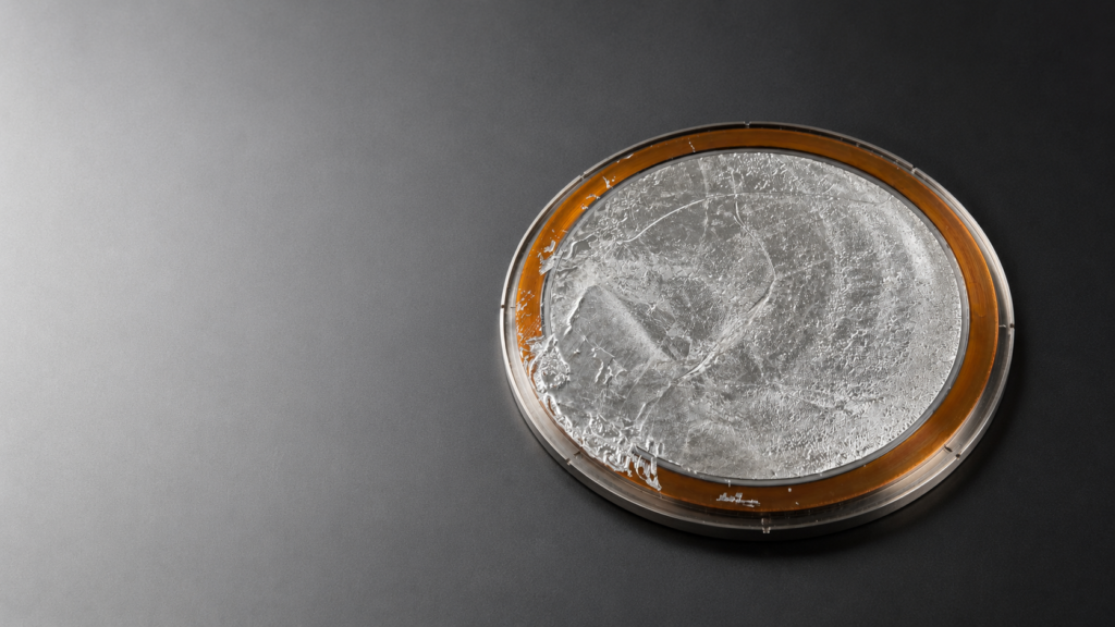
Target Debonding, Rebonding & Backing Plate Reuse
TFM can review customer-supplied bonded target assemblies for debonding, backing plate cleaning, reuse, and rebonding with a new target where technically feasible.
Before reuse, the backing plate should be inspected for flatness, thickness, recess depth, corrosion, thread condition, hole damage, overheating marks, residual bonding material, and rear contact surface condition. If reuse is not reliable, a new backing plate can be quoted according to the original drawing or assembly dimensions.
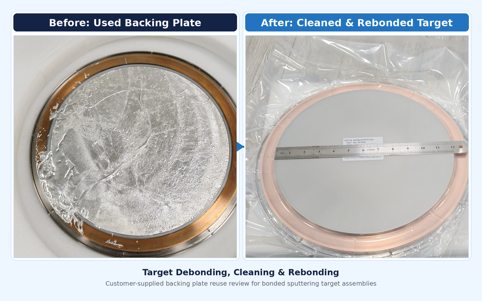
We can review:
- Target debonding
- Backing plate cleaning
- Residual indium or adhesive removal
- Customer-supplied backing plate reuse
- Rebonding with a new sputtering target
- Replacement backing plate machining
- OEM-source backing plate reproduction
- Bonding method change or upgrade
When Should a Sputtering Target Be Bonded?
Bonding is commonly reviewed when the target requires additional mechanical support, improved heat transfer, controlled mounting geometry, or a defined interface with the sputtering source.
A bonded target assembly may be recommended when:
- The target material is brittle, such as ceramic, oxide, or semiconductor materials.
- The target is thin, large, or mechanically fragile.
- Better heat transfer toward the cathode is required.
- The target requires support from a backing plate.
- A specific installed height or OEM cathode fit must be maintained.
- The target will operate under higher power or repeated thermal cycling.
- A customer-supplied backing plate may need to be reused.
- The assembly requires dimensional inspection or bonding records.
Bonding should be reviewed together with target material, backing plate material, cooling interface, power mode, ramp rate, and operating cycle.
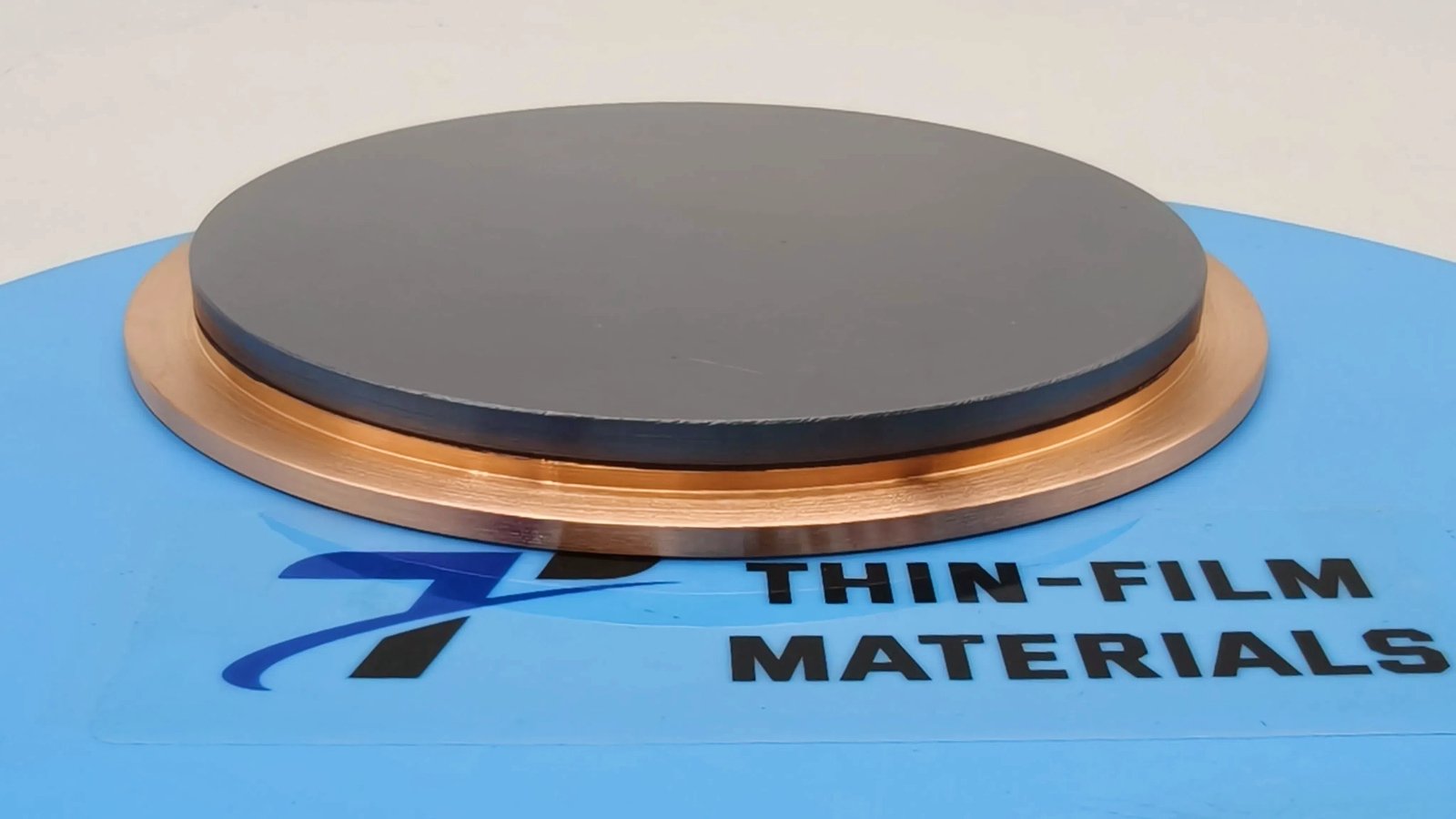
Not sure which bonding method or backing plate design is suitable? Share your target material, backing plate drawing, cathode model, operating power, and cooling conditions. Our team can help review a suitable bonding and backing plate option.

What Makes Up a Bonded Target Assembly?
A bonded sputtering target assembly normally includes the target, bonding layer, backing plate, cathode interface, and cooling path.
Heat Path
Target → Bonding Layer → Backing Plate → Cathode → Cooling Water
Target
The target supplies the material to be deposited as a thin film. Its material, size, thickness, brittleness, density, and thermal behavior influence the bonding and backing plate design.
Bonding Layer
The bonding layer connects the target to the backing plate and provides a thermal and mechanical interface. Indium bonding and elastomeric bonding are commonly reviewed options, depending on material and operating requirements.
Backing Plate
The backing plate supports the target, transfers heat toward the cathode, helps maintain dimensional stability, and provides the mechanical interface with the sputtering source.
Cathode / Source Interface
The cathode or source controls mounting, rear contact, cooling, installed height, and operating compatibility. For OEM sources, drawing accuracy is especially important.
Cooling Path
Cooling effectiveness depends on the complete path from target to cooling water. Bond quality, backing plate material, rear contact, cathode flatness, cooling flow, and power density should be reviewed together.
Backing Plate Material Options
| Material | Best Used When | Main Limitation |
|---|---|---|
| OFHC Copper | Cooling and machinability are priorities | Higher CTE and weight |
| Molybdenum | Low expansion and dimensional stability are critical | Cost, density, and machining difficulty |
| Aluminum | Large assemblies require weight reduction | High CTE and surface preparation requirements |
| Titanium | Corrosion resistance or environmental compatibility is required | Low thermal conductivity |
| Copper Alloy | Higher strength, thread durability, or handling resistance is needed | Lower conductivity than OFHC copper |
| Stainless Steel | Threads, retainers, fixtures, or structural features are required | Poor primary heat spreading |
| Composite Structure | One metal cannot balance all required properties | Additional interfaces and manufacturing complexity |
Final backing plate selection should consider target material, target size, sputtering power, cooling arrangement, bonding method, plate thickness, cathode support, and operating cycle.
OEM Replacement and Customer-Supplied Backing Plate Review
TFM can review customer-supplied backing plates for possible reuse or quote new backing plates based on drawings and assembly requirements.
For replacement assemblies, the backing plate must be checked as part of the complete bonded target system. Important review points may include flatness, thickness, recess depth, hole position, thread condition, rear contact geometry, corrosion, overheating marks, and cooling interface compatibility.
We can review:
- Existing backing plate reuse
- Debonding and cleaning feasibility
- New replacement backing plate machining
- Drawing-based reproduction
- Hole pattern and PCD
- Recess depth and installed height
- Total assembly thickness
- Rear contact geometry
- Cooling interface
- Bonding method and inspection requirements
A drawing is strongly preferred. Photos can help identify the assembly, but they cannot confirm critical dimensions or tolerances.
Inspection and Documentation
Inspection and documentation can be agreed according to target material, backing plate design, bonding method, drawing tolerance, and end-use requirements.
For drawing-based bonded assemblies, inspection should reference the approved drawing and revision.
Available or project-specific documentation may include:
- Material certificate
- CoA
- Dimensional inspection report
- Flatness and parallelism records
- Backing plate material confirmation
- Bonding inspection record
- Photo record before shipment
- Customer-format documentation
- Drawing revision traceability
Special documentation, third-party testing, or customer-specific report formats should be confirmed before production and included in the quotation scope.
Information Needed for Quotation
Please provide:
- Target material, purity, density, dimensions, and quantity
- Bonding method required, if known
- Backing plate material, dimensions, and thickness
- Drawing, STEP file, or current assembly photo
- Hole pattern, PCD, recess, groove, thread, and edge requirements
- Cathode or sputtering source model
- Installed height and total assembly thickness
- Cooling interface and rear contact surface requirements
- Sputtering mode, power, ramp rate, run time, and operating cycle
- Whether an existing backing plate will be reused
- Required documents and inspection reports
- Delivery location and required lead time
Minimum Information
Target material, target dimensions, backing plate requirement, quantity, bonding method if known, drawing or assembly photo, and delivery location.
Example RFQ
We need an indium-bonded ceramic sputtering target assembly. Target material: Al₂O₃, Ø76.2 × 6 mm. Backing plate: OFHC copper, Ø76.2 × 3 mm, with existing cathode fit. Quantity: 2 pcs. Please quote bonding service, backing plate machining if required, dimensional inspection, and lead time.
Frequently Asked Questions
1. What is sputtering target bonding used for?
Sputtering target bonding joins the target material to a backing plate to improve mechanical support, heat transfer, cathode fit, and assembly reliability during sputtering.
2. When should a sputtering target be bonded?
Bonding is commonly reviewed for brittle ceramic targets, oxide targets, semiconductor targets, thin metallic targets, large targets, or targets requiring improved thermal contact and mechanical support.
3. What bonding methods are available?
Common options include indium bonding and elastomeric bonding. The suitable method depends on target material, size, power, temperature, cathode design, and operating conditions.
4. Can an existing backing plate be reused?
Yes, if it remains suitable after debonding and cleaning. Flatness, thickness, recess depth, corrosion, holes, threads, overheating, and rear contact condition should be inspected before reuse.
Request a Bonding or Backing Plate Review
Send your target material, dimensions, backing plate drawing, cathode information, bonding method, operating conditions, and documentation requirements. TFM can review the bonded target assembly and provide a quotation based on feasibility, drawing requirements, and operating conditions.
Technical Guide: Sputtering Target Backing Plate Material Selection
The following guide explains how to compare common sputtering target backing plate materials, including OFHC copper, molybdenum, aluminum, titanium, stainless steel, copper alloys, and composite structures. It is intended to support early material selection and RFQ preparation for bonded sputtering target assemblies.
The Article
5. Is OFHC copper always the best backing plate material?
No. OFHC copper is a common starting point because of its thermal conductivity, machinability, and bonding compatibility. Other materials may be considered when thermal expansion, weight, corrosion, strength, or cathode design becomes more important.
Request a Bonding or Backing Plate Review
Send your target material, dimensions, backing plate drawing, cathode information, bonding method, operating conditions, and documentation requirements. TFM can review the bonded target assembly and provide a quotation based on feasibility, drawing requirements, and operating conditions.
Technical Guide: Sputtering Target Backing Plate Material Selection
The following guide explains how to compare common sputtering target backing plate materials, including OFHC copper, molybdenum, aluminum, titanium, stainless steel, copper alloys, and composite structures. It is intended to support early material selection and RFQ preparation for bonded sputtering target assemblies.
The Article
6. Can TFM make backing plates for OEM sputtering sources?
Yes. TFM can review drawings or assembly dimensions for OEM-source replacement backing plates, including hole pattern, PCD, recess, installed height, total thickness, and rear contact geometry.
Request a Bonding or Backing Plate Review
Send your target material, dimensions, backing plate drawing, cathode information, bonding method, operating conditions, and documentation requirements.
TFM can review the bonded target assembly and provide a quotation based on feasibility, drawing requirements, and operating conditions.
Technical Guide: Sputtering Target Backing Plate Material Selection
The following guide explains how to compare common sputtering target backing plate materials, including OFHC copper, molybdenum, aluminum, titanium, stainless steel, copper alloys, and composite structures. It is intended to support early material selection and RFQ preparation for bonded sputtering target assemblies.
The Article
Request a Bonding or Backing Plate Review
Send your target material, dimensions, backing plate drawing, cathode information, bonding method, operating conditions, and documentation requirements. TFM can review the bonded target assembly and provide a quotation based on feasibility, drawing requirements, and operating conditions.
Technical Guide: Sputtering Target Backing Plate Material Selection
The following guide explains how to compare common sputtering target backing plate materials, including OFHC copper, molybdenum, aluminum, titanium, stainless steel, copper alloys, and composite structures. It is intended to support early material selection and RFQ preparation for bonded sputtering target assemblies.
Sputtering Target Backing Plates: What Each Material Does and How to Choose
When a bonded sputtering target cracks, overheats, bows, or separates from its support, the target material is often blamed first.
But the underlying problem may be behind it.
A backing plate does more than hold the target in place. It transfers heat toward the cathode, supports the bonding layer, maintains dimensional stability, and provides the mechanical interface between the target and the sputtering source.
The correct backing plate is therefore not simply the metal with the highest thermal conductivity. It is the material—or engineered combination of materials—that solves the dominant design problem without creating a more serious one elsewhere.
For many bonded sputtering targets, OFHC copper remains the standard starting point. Other metals or composite structures should be considered only when thermal expansion, weight, corrosion resistance, rigidity, or cathode geometry becomes a more important constraint.
Table of Contents
Chapter 1
Why the Backing Plate Matters and How to Select It
A bonded sputtering target assembly normally contains three functional components:
- The target supplies the material deposited as a thin film.
- The bonding layer joins the target to its support.
- The backing plate supports the target and transfers heat toward the cathode.
During operation, heat follows a continuous path:
Target → Bonding Layer → Backing Plate → Cathode → Cooling Water
A weakness anywhere along this path can increase the target temperature.
Even a highly conductive backing plate cannot compensate for large bonding voids, excessive bond-line thickness, poor rear-surface contact, inadequate cooling-water flow, or a warped cathode.
Similarly, a compliant bonding layer cannot fully protect a brittle target when the target and backing plate expand at substantially different rates.
A backing plate must therefore perform four connected functions:
- Remove heat from the target
- Provide mechanical support
- Control thermal expansion and distortion
- Remain compatible with the bonding method and cathode
These functions should not be evaluated separately. Improving one property may weaken another.
For example, molybdenum provides lower thermal expansion than copper but is more expensive and difficult to machine. Aluminum reduces weight but has a higher coefficient of thermal expansion. Titanium resists corrosion but transfers heat much less effectively than copper.
The best material is therefore the one that addresses the dominant constraint of the assembly.
Initial Material Comparison
| Material | Thermal Conductivity, W/m·K | CTE, µm/m·K | Density, g/cm³ | Best Used When | Main Limitation |
|---|---|---|---|---|---|
| OFHC copper | ~394 | ~17.7 | 8.94 | Cooling and machinability are priorities | Relatively high weight and CTE |
| Molybdenum | ~142 | ~5.2 | 10.22 | Low expansion and dimensional stability are critical | Cost, density, and difficult machining |
| Aluminum 6061-T6 | ~167 | ~23.6 | 2.71 | Large assemblies require weight reduction | High CTE and surface preparation requirements |
| CP titanium Grade 2 | ~21.8 | ~8.6 | 4.51 | Corrosion resistance or environmental compatibility is required | Low thermal conductivity |
| Copper alloy | Grade-dependent | Grade-dependent | Grade-dependent | Pure copper lacks sufficient mechanical strength | Lower conductivity than OFHC copper |
| Stainless steel | ~15–25, grade-dependent | Grade-dependent | ~7.7–8.0 | Threads, retainers, and structural features are required | Poor primary heat spreading |
| Composite structure | Design-dependent | Design-dependent | Design-dependent | One metal cannot balance all required properties | Additional interfaces and manufacturing complexity |
These values are representative engineering data for initial material comparison. They are not guaranteed specification values or final assembly design limits.
Actual properties vary with grade, purity, temper, product condition, temperature, and manufacturing history.
The table is useful for initial screening, but the final decision must also consider:
- Target material and dimensions
- Target brittleness
- Sputtering power and power density
- Backing plate thickness
- Cooling-water arrangement
- Bonding method
- Cathode support geometry
- Allowable weight
- Thermal cycling conditions
A useful selection sequence is:
- Confirm the cathode interface and maximum assembly dimensions.
- Identify the expected heat load and cooling conditions.
- Evaluate the target-to-backing-plate CTE relationship.
- Confirm the required stiffness and allowable weight.
- Select a compatible bonding method.
- Consider a composite design only if one material cannot meet the critical requirements.
Chapter 2
What Each Backing Plate Material Does
OFHC Copper: The Standard Starting Point
Oxygen-free high-conductivity copper is widely used because it provides an effective balance of thermal conductivity, machinability, and bonding compatibility.
It can be machined with:
- Holes and threads
- Steps and recesses
- Grooves and cooling features
- Chamfers
- Locating features
- Cathode-specific rear geometries
OFHC copper backing plates are commonly used for circular, rectangular, stepped, segmented, and bonded target assemblies.
Copper is usually appropriate when:
- Cooling is the primary requirement.
- Target dimensions are moderate.
- Cooling is distributed uniformly.
- Assembly weight is acceptable.
- The CTE difference is manageable.
- Plate thickness provides sufficient rigidity.
This makes copper particularly useful behind brittle ceramic targets, oxide targets, semiconductor targets, and thin metallic targets requiring mechanical reinforcement.
Its main limitations are weight, softness, and relatively high thermal expansion.
For large targets, full copper backing plates can become heavy. Thin copper features may also deform under clamping or repeated installation. For low-CTE target materials, copper expansion may contribute to bowing or edge stress.
Copper should therefore remain the default starting point—but not the automatic final choice.
Molybdenum: Controlling Expansion and Distortion
Molybdenum is considered when dimensional stability is more important than maximum thermal conductivity.
Its low coefficient of thermal expansion can reduce differential movement between the backing plate and low-CTE target materials.
For illustration, consider an unconstrained 300 mm plate exposed to a 100°C temperature rise:
- Copper would expand by approximately 0.53 mm.
- Molybdenum would expand by approximately 0.16 mm.
- The theoretical difference would be approximately 0.37 mm.
A bonded assembly cannot expand freely, so this calculation does not predict actual target deformation. It shows why apparently small CTE differences can create meaningful interfacial stress in a large assembly.
Molybdenum may be suitable for:
- Large low-CTE targets
- Precision semiconductor applications
- Brittle materials sensitive to edge stress
- Repeated thermal cycling
- Assemblies in which copper produces unacceptable bowing
Its disadvantages include high density, high cost, and difficult machining.
Molybdenum should therefore solve a specific expansion or dimensional-stability problem. It should not be treated as a general upgrade from copper.
Aluminum: Reducing Assembly Weight
Aluminum is mainly considered when the mass of a full copper backing plate becomes a practical limitation.
This may occur in large-area display, photovoltaic, architectural coating, or other systems where source weight affects handling, mounting, or equipment loading.
Aluminum offers useful thermal conductivity at much lower density than copper. However, the design must also account for:
- Higher thermal expansion
- A stable surface oxide
- Lower high-temperature strength
- Surface preparation before bonding
- Cooling-water compatibility
- Galvanic interaction with other metals
- Required plate stiffness
Aluminum is therefore a weight-saving solution rather than a direct thermal equivalent to copper.
It is most appropriate when reduced mass is a defined requirement and its higher CTE can be managed through geometry, bonding design, or a composite structure.
Titanium: Improving Corrosion Resistance
Titanium may be considered when cooling-water chemistry, process conditions, or surrounding equipment makes copper less suitable.
It provides good corrosion resistance, moderate thermal expansion, and lower density than copper or molybdenum.
Its principal limitation is low thermal conductivity.
Titanium is generally better suited to specialized or low-to-moderate heat-load assemblies than to the main heat-spreading plate behind a high-power target.
Where both corrosion resistance and heat transfer are required, titanium may be more suitable as one functional part of the assembly rather than as the complete backing plate.
Copper Alloys: Adding Mechanical Strength
Pure copper may deform under high clamping loads or repeated installation.
A specified copper alloy can provide:
- Higher strength
- Better thread durability
- Greater resistance to handling distortion
- Improved stability around thin machined features
The trade-off is normally lower thermal conductivity than OFHC copper.
Copper alloys are therefore useful when mechanical durability becomes more important than achieving the highest possible conductivity.
The exact alloy grade should be specified because its strength, conductivity, corrosion resistance, and machinability can vary significantly.
Stainless Steel: Supporting Structural Features
Stainless steel is generally better suited to structural parts than to the main cooling plate.
Typical uses include:
- Threaded sections
- Retaining rings
- Clamps
- Fixtures
- Structural frames
- Reinforcing features
Its relatively low thermal conductivity makes it unsuitable for primary heat spreading in most high-power target assemblies.
The exact stainless steel grade should also be specified because ferritic and austenitic grades differ in conductivity, thermal expansion, magnetic behavior, and corrosion resistance.
Composite Backing Plates: Combining Different Functions
A composite backing plate becomes reasonable when no single metal can satisfy the critical requirements at the same time.
A one-piece copper plate remains preferable when it already provides:
- Adequate cooling
- Manageable expansion
- Sufficient rigidity
- Acceptable weight
- Reliable bonding compatibility
A solid plate has fewer interfaces, simpler manufacturing, and fewer potential failure locations.
Composite structures become useful when different layers must perform different functions.
Cu-Mo and Cu-W Structures
Cu-Mo and Cu-W combine copper’s heat-transfer and bonding characteristics with the lower thermal expansion or greater stiffness of molybdenum or tungsten.
They may be considered for:
- Low-CTE target materials
- Precision semiconductor assemblies
- Large targets sensitive to bowing
- Brittle targets exposed to thermal cycling
- Designs in which solid copper creates excessive expansion
The layer thickness, joining method, machining sequence, and residual stress must be controlled carefully.
A poorly designed composite may add thermal resistance and manufacturing complexity without providing sufficient benefit.
Cu/Al/Cu Structures
A Cu/Al/Cu structure uses an aluminum core to reduce weight while retaining copper surfaces for target bonding and cathode contact.
Its reliability depends on:
- Layer thickness
- Joining method
- Interface flatness
- Residual stress
- Machining sequence
- Cooling design
- Thermal cycling resistance
In specialized designs, different layers may be assigned to target bonding, expansion control, weight reduction, cathode contact, corrosion resistance, or structural reinforcement.
However, every added interface can introduce:
- Thermal contact resistance
- Residual joining stress
- Distortion
- Flatness variation
- Machining difficulty
- Delamination risk
A composite structure should therefore be selected only when its functional benefit clearly outweighs the added complexity.
Chapter 3
Bonding Compatibility, Failure Analysis, and Technical Review
Backing Plate and Bonding Compatibility
Backing plate material cannot be evaluated separately from the bonding system.
Indium bonding is often used for brittle ceramic, oxide, and semiconductor targets because it provides thermal contact while accommodating limited differential movement.
Elastomeric or epoxy-based bonding systems may be selected for other target materials, operating temperatures, or stress-control requirements.
Important bonding variables include:
- Bond-line thickness
- Bond coverage
- Void control
- Surface cleanliness
- Wetting quality
- Flatness
- Operating temperature
- Thermal cycling frequency
- Target brittleness
- Backing plate expansion
The target-side surface may require controlled roughness, plating, grooves, a machined recess, or defined edge clearance.
The rear surface must maintain uniform contact with the cathode.
A compliant bonding layer can reduce stress, but it cannot correct an unsuitable backing plate material, insufficient thickness, poor flatness, or incompatible geometry.
What Backing Plate Failures Can Indicate
Backing plate-related problems commonly appear as cracking, hot spots, bowing, corrosion, or repeated debonding.
| Observed Problem | Factors to Investigate |
| Edge cracking | CTE mismatch, edge constraint, uneven bond thickness, or excessive thermal cycling |
| Local hot spots | Bond voids, poor rear contact, insufficient cooling flow, or surface distortion |
| Assembly bowing | Plate stiffness, residual machining stress, CTE mismatch, or non-uniform bonding |
| Repeated debonding | Surface preparation, wetting, bond temperature limit, or thermal overload |
| Rear-surface corrosion | Cooling-water chemistry, galvanic interaction, or incompatible materials |
These symptoms should be evaluated together with:
- Target quality
- Bond condition
- Cathode flatness
- Cooling performance
- Rear-surface contact
- Sputtering power
- Operating cycle
- Installation and clamping conditions
A target crack does not automatically prove that the target material was defective. Likewise, repeated debonding does not always indicate that the bonding material was unsuitable.
Failure analysis should consider the complete assembly.
Information Needed for Technical Review
A technical review is more reliable when the backing plate, bonding method, cathode, and operating conditions are considered together.
| Information | Details to Provide |
| Target | Material, composition, purity, density, and dimensions |
| Backing plate | Material preference, dimensions, thickness, recesses, holes, and threads |
| Cathode | Source model, assembly drawing, or interface dimensions |
| Bonding | Indium, elastomer, epoxy, customer-specified method, or unbonded |
| Operating conditions | Sputtering mode, power, cooling arrangement, and operating cycle |
| Quality requirements | Tolerances, inspection reports, material certificates, quantity, and documentation |
A drawing is preferable to a photograph for replacement assemblies.
Photographs may show the general configuration, but they cannot reliably confirm:
- Flatness
- Parallelism
- Thickness
- Recess depth
- Hole position
- Thread specification
- Rear contact geometry
- Dimensional tolerances
For an OEM replacement, the preferred reference is the original engineering drawing, assembly drawing, cathode interface drawing, or an inspected sample component.
Backing Plate Cleaning and Reuse
A customer-supplied backing plate may be cleaned and reused if it remains suitable after debonding and inspection.
The review should include:
- Overall flatness
- Remaining thickness
- Recess depth
- Corrosion or pitting
- Hole condition
- Thread condition
- Evidence of overheating
- Previous bond residue
- Edge damage
- Rear cathode-contact surface
- Dimensional distortion
The plate should also be checked for excessive material removal caused by previous cleaning or resurfacing.
Reuse should be approved only when the cleaned backing plate remains dimensionally, mechanically, and thermally suitable for the new assembly.
If reuse is not reliable, a replacement backing plate may be manufactured from the original drawing, an approved reverse-engineered drawing, or confirmed assembly dimensions.
Inspection and Documentation
Depending on the project, documentation may include:
- Material certificate
- Certificate of Analysis
- Dimensional inspection report
- Flatness and parallelism records
- Surface-finish record
- Bonding inspection
- Assembly inspection results
- Drawing confirmation
- Packaging documentation
Inspection and documentation requirements should be confirmed before quotation because they may affect manufacturing cost and lead time.
Chapter 4
Frequently Asked Questions
1. Does a higher-conductivity backing plate always improve target cooling?
No. Cooling also depends on bond quality, bond-line thickness, rear-surface contact, cathode flatness, cooling-water flow, and target power density.
A highly conductive backing plate cannot compensate for a poor thermal interface.
2. Can indium bonding compensate for CTE mismatch?
Indium can accommodate limited differential movement because it is relatively compliant.
However, it cannot correct a severe mismatch between the target material, backing plate material, assembly dimensions, and operating temperature.
3. Does a composite backing plate always perform better than solid copper?
No. A one-piece copper plate is usually preferable when it already meets cooling, rigidity, weight, and expansion requirements.
Composite structures should solve a defined engineering problem.
4. Should the backing plate material match the target material?
Not necessarily.
The backing plate should be selected according to heat transfer, CTE compatibility, mechanical support, environmental conditions, bonding requirements, and cathode design.
5. Can a customer-supplied backing plate be cleaned and rebonded?
Yes, provided it remains suitable after debonding, cleaning, and inspection.
Flatness, thickness, recess depth, corrosion, holes, threads, overheating, and rear contact condition should be checked before reuse.
6. How thick should a backing plate be?
There is no universal thickness.
It depends on the plate area, material strength, clamping method, machined features, cathode support, thermal load, and allowable deflection.
7. What tolerances are important?
8. Can aluminum and copper be used in the same backing plate?
Yes. A Cu/Al/Cu structure may reduce weight while retaining copper bonding and cathode-contact surfaces.
The internal interfaces must withstand machining, handling, and thermal cycling.
9. What inspection documents can be requested?
Depending on the project, documentation may include a material certificate, CoA, dimensional inspection report, flatness records, surface-finish records, and bonding or assembly inspection results.
10. What information is needed for quotation?
Provide the target material and dimensions, backing plate drawing, cathode information, bonding method, operating conditions, quantity, tolerances, and documentation requirements.
Chapter 5
Conclusion
OFHC copper remains the starting point for most bonded sputtering targets because it offers an effective balance of cooling, machinability, and bonding compatibility.
Alternative materials should be selected only when another constraint becomes dominant.
Molybdenum can help control thermal expansion and distortion. Aluminum can reduce the weight of large assemblies. Titanium may improve corrosion resistance. Copper alloys and stainless steel can strengthen structural features.
Composite structures are appropriate when no single material can provide the required thermal, mechanical, dimensional, and weight performance.
Their value comes from purposeful layer design and reliable interfaces—not from complexity alone.
For drawing-based target assemblies, TFM can review the proposed backing plate material, geometry, bonding method, cathode interface, and possible reuse of an existing backing plate before quotation.