Introduction
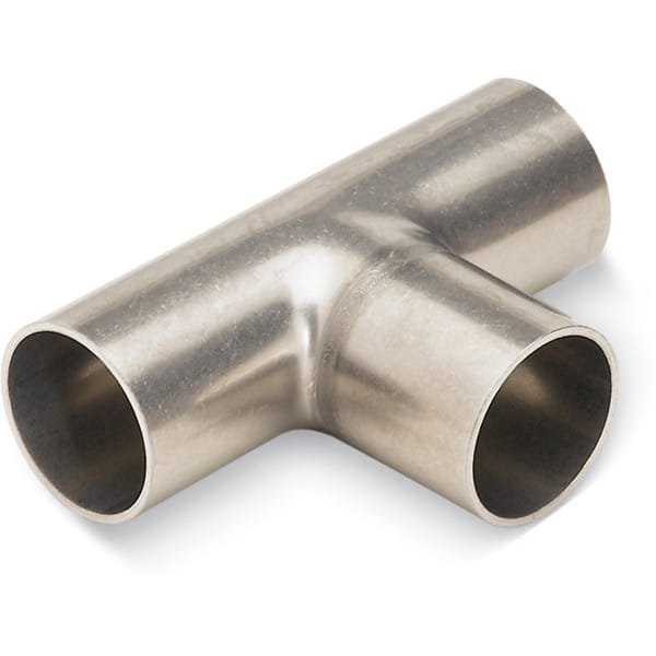
Weldable Tube Tees are essential vacuum and process components designed to create branch connections in tubing systems through permanent welding. They are widely used in high-vacuum (HV) and ultra-high-vacuum (UHV) assemblies where leak integrity, mechanical strength, and clean internal geometry are critical. By eliminating demountable joints at the branch point, weldable tube tees help achieve compact layouts with minimal virtual leaks.
Detailed Description
Weldable tube tees are precision-machined fittings with three tube ends configured in a “T” geometry, allowing one main run with a perpendicular branch. They are typically manufactured from vacuum-grade stainless steel—most commonly 304L or 316L—to ensure excellent corrosion resistance, low outgassing, and compatibility with standard welding techniques such as TIG (GTAW).
The weld ends are supplied with straight, uniform wall thickness to support consistent weld penetration and smooth internal transitions after welding. Careful control of concentricity and surface finish minimizes turbulence, particle trapping, and dead volume—key considerations for vacuum performance and process repeatability.
These tees can be integrated into systems that later terminate in CF, ISO, or KF interfaces, making them highly flexible building blocks for custom manifolds and chambers.
Applications
High-vacuum and UHV tubing manifolds
Thin film deposition systems (PVD, sputtering, evaporation)
Semiconductor process gas and vacuum lines
Analytical and surface science instruments
Custom-built research and industrial vacuum assemblies
Technical Parameters
| Parameter | Typical Value / Range | Importance |
|---|---|---|
| Material | Stainless Steel 304L / 316L | Low outgassing, weldability |
| Configuration | Tube Tee (3-way) | Branch connection |
| Tube OD | Standard metric or inch sizes (custom) | System compatibility |
| Wall Thickness | Matched to vacuum tubing | Uniform weld quality |
| Joining Method | TIG / orbital welding | Permanent, leak-tight joints |
| Surface Finish | As-machined / optional electropolish | Cleanliness & flow |
Comparison with Related Components
| Component | Key Advantage | Typical Application |
|---|---|---|
| Weldable Tube Tee | No demountable seals, compact | Permanent HV/UHV manifolds |
| KF Tee | Fast assembly | Modular lab systems |
| CF Tee | UHV sealing, demountable | Instrument interfaces |
FAQ
| Question | Answer |
|---|---|
| Are these suitable for UHV systems? | Yes, when properly welded and cleaned, they are ideal for UHV. |
| What welding method is recommended? | TIG or orbital welding is commonly used for best results. |
| Are custom tube sizes available? | Yes, OD, wall thickness, and branch dimensions can be customized. |
| Can electropolishing be provided? | Yes, electropolished finishes are available on request. |
| How are they cleaned before shipment? | Cleaned for vacuum service and packaged to prevent contamination. |
Packaging
Our Weldable Tube Tees are cleaned, capped on all tube ends, and individually packed to protect the sealing and weld surfaces. Export-grade cartons or wooden crates are used to ensure safe transportation and maintain cleanliness.
Conclusion
Weldable Tube Tees provide a robust, space-efficient solution for creating permanent branch connections in vacuum tubing systems. With vacuum-grade materials, precise geometry, and customizable dimensions, they are ideal for demanding HV and UHV applications where long-term reliability and cleanliness are essential.
For detailed specifications and a quotation, please contact us at sales@thinfilmmaterials.com.
Ordering Table
Weldable Tube Tees
| Drawing | WallThickness | DimA | TubeOD | Finish | Note | Part Number |

| 0.04 | 0.75 | 0.38 | Tumbled | G-7W-038 | |
|
| 0.05 | 0.75 | 0.5 | Tumbled | G-7W-050 | |
|
| 0.04 | 1 | 0.75 | Tumbled | — | G-7W-075 |
|
| 0.07 | 1.88 | 0.75 | Tumbled | — | G-7W-075HW |
|
| 0.07 | 1 | 0.75 | Tumbled | — | G-7W-075T |
|
| 0.07 | 1.88 | 1 | Tumbled | — | G-7W-100 |
|
| 0.12 | 9.5 | 10 | Tumbled | — | G-7W-1000 |
|
| 0.07 | 2.25 | 1.5 | Tumbled | — | G-7W-150 |
|
| 0.07 | 2.25 | 1.5 | Beadblasted | — | G-7W-150-B |
|
| 0.07 | 2.41 | 1.5 | Tumbled | — | G-7W-150H |
|
| 0.07 | 2.41 | 1.5 | Beadblasted | — | G-7W-150H-B |
|
| 0.07 | 3 | 2 | Tumbled | — | G-7W-200 |
|
| 0.07 | 2.61 | 2 | Tumbled | — | G-7W-200H |
|
| 0.07 | 2.61 | 2 | Beadblasted | — | G-7W-200H-B |
|
| 0.07 | 3 | 2.5 | Tumbled | — | G-7W-250 |
|
| 0.07 | 3.75 | 2.5 | Tumbled | — | G-7W-250V |
|
| 0.07 | 3.25 | 3 | Tumbled | — | G-7W-300 |
|
| 0.08 | 3.88 | 4 | Tumbled | — | G-7W-400 |
|
| 0.08 | 4.87 | 4 | Tumbled | — | G-7W-400V |
|
| 0.08 | 4.25 | 5 | Tumbled | — | G-7W-500 |
|
| 0.08 | 5 | 6 | Beadblasted | — | G-7W-600-B |
|
| 0.08 | 6.06 | 6 | Beadblasted | — | G-7W-600V-B |
|
| 0.12 | 7 | 8 | Tumbled | — | G-7W-800 |

Reviews
There are no reviews yet.