ConFlat® (CF) UHV Straight Reducer Nipples: Precision Flange Transitions for Ultra-High Vacuum Integrity
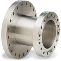
ConFlat® (CF) UHV Straight Reducer Nipples from TFM are purpose-built components designed to connect two different CF flange sizes in a straight, axial configuration within ultra-high vacuum (UHV) systems. Made from high-purity 304L stainless steel and terminated with knife-edge ConFlat flanges, these reducer nipples are ideal for high-integrity sealing across instrumentation ports, vacuum chambers, and diagnostic systems.
Unlike conical designs, CF UHV Straight Reducer Nipples maintain a linear path between connected flanges, making them ideal for systems that demand direct, compact transitions without altering flow direction.
Key Features of ConFlat® (CF) UHV Straight Reducer Nipples:
Straight Reducer Geometry
Each nipple enables a direct connection between mismatched CF flange sizes—such as CF63 to CF40 or CF40 to CF16—while maintaining a straight internal passage for unimpeded flow.CF Knife-Edge Flange Ends
The reducer nipple is equipped with standard CF flanges on both ends, compatible with copper gaskets for reliable metal-to-metal sealing in high and ultra-high vacuum environments.304L Stainless Steel Construction
Fabricated from low-carbon stainless steel, these ConFlat® (CF) UHV Straight Reducer Nipples provide excellent corrosion resistance, weldability, and stability during system bake-out cycles.UHV Performance
Suitable for systems operating at pressures down to 10⁻¹⁰ torr, the straight reducer design ensures no leak paths or alignment issues when assembled with proper hardware.Versatile Sizing & Custom Fabrication
Standard reducer sizes and lengths are readily available. TFM also offers custom manufacturing of ConFlat® (CF) UHV Straight Reducer Nipples to meet specific configuration or spatial requirements.
Applications:
Connecting CF flange components with different nominal sizes in vacuum chambers
Integrating sensors, gauges, or feedthroughs requiring smaller CF ports
Upgrading or retrofitting UHV systems with mixed flange standards
Simplifying axial transitions in beamline systems or UHV manifolds
Ensuring vacuum integrity in research instruments, analytical systems, and cleanroom tools
TFM supports a wide range of UHV flange accessories, including CF full nipples, conical reducers, rotatable flanges, and complete gasket and bolt kits, offering everything needed to build or modify a high-performance vacuum system with confidence.
Ordering Table
| Flange Size/OD (Large) | Flange Size/OD (Small) | Part Number |
| DN35CF-DN40CF (2.75" OD) | DN35CF-DN40CF (2.75" OD) | RN0600X275 |
| DN35CF-DN40CF (2.75" OD) | DN35CF-DN40CF (2.75" OD) | RN0800X275 |
| DN63CF (4.50" OD) | DN63CF (4.50" OD) | RN0800X450 |
| DN100CF (6.00" OD) | DN100CF (6.00" OD) | RN0800X600 |
| DN35CF-DN40CF (2.75" OD) | DN35CF-DN40CF (2.75" OD) | RN1000X275 |
| DN63CF (4.50" OD) | DN63CF (4.50" OD) | RN1000X450 |
| DN100CF (6.00" OD) | DN100CF (6.00" OD) | RN1000X600 |
| DN160CF (8.00" OD) | DN160CF (8.00" OD) | RN1000X800 |
| DN200CF (10.00" OD) | DN200CF (10.00" OD) | RN1325X1000 |
| DN160CF (8.00" OD) | DN160CF (8.00" OD) | RN1325X800 |
| DN200CF (10.00" OD) | DN200CF (10.00" OD) | RN1200X1000 |
Reviews
There are no reviews yet.