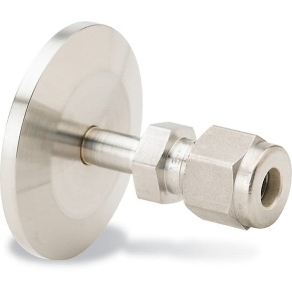
KF to Swagelok® Adapter: Reliable Vacuum-to-Tube Transitions with Leak-Free Integrity
The KF to Swagelok® Adapter, offered by TFM, provides a precision interface between KF (QF) vacuum flanges and Swagelok® compression fittings, enabling smooth integration between high-vacuum systems and high-purity process lines. Designed for environments where both cleanliness and sealing reliability are paramount, this adapter supports quick-connect vacuum flanges and torque-free Swagelok sealing technology in one robust component.
Machined from 304 series stainless steel, the adapter offers exceptional strength and corrosion resistance, making it ideal for laboratory vacuum setups, semiconductor manufacturing, and chemical process systems. Its compact, modular design simplifies system layout while maintaining the leak-tight performance expected in high-vacuum or clean gas delivery applications.
Key Features of KF to Swagelok® Adapter:
Cross-System Connectivity
Enables direct connection between KF-style vacuum flanges (e.g., KF16, KF25, KF40) and Swagelok® compression tube fittings without additional transitions.Torque-Free Sealing Technology
Swagelok’s patented design creates a leak-free seal through radial compression rather than torque, minimizing risk of thread damage or leaks over time.304 Stainless Steel Construction
Ensures durability, vacuum compatibility, and long-term chemical resistance in demanding environments.Modular and Removable
The KF flange allows fast, tool-free connection to vacuum ports via clamp-and-o-ring assemblies, while the Swagelok end can be connected to standard tubing using compression ferrules.Vacuum and Pressure Performance
– KF flange rated for HV conditions down to ~10⁻⁷ torr
– Swagelok end rated for pressures up to 3000 psig, depending on fitting size and tubing specificationsFlexible System Integration
Ideal for systems requiring transition between vacuum chambers and gas delivery tubing, including purge lines, sample inlets, and vent systems.
Applications:
Analytical instruments with vacuum and gas interface requirements
High-vacuum chambers needing integration with standard 1/4″, 3/8″, or 1/2″ process lines
Semiconductor tools where Swagelok purity and KF modularity are both required
Gas handling systems that must connect to vacuum environments
Pilot plants and test benches for flexible process control
TFM also provides CF to Swagelok® Adapters, KF to VCR® face-seal adapters, and KF-to-compression tube transitions, enabling full system flexibility and purity assurance.
In conclusion, the KF to Swagelok® Adapter bridges vacuum technology and process engineering with a compact, leak-tight, and UHV-capable solution. Whether you’re building a new vacuum line or retrofitting process equipment, TFM’s adapter ensures compatibility, performance, and clean operation every time.
Ordering Table
| Flange Size/OD | Drawing | Fitting | Part Number |
| KF16 (1.18" OD) |

| 1/16" Swagelok | QF16X1SWG |
| KF16 (1.18" OD) |
| 1/8" Swagelok | QF16X2SWG |
| KF16 (1.18" OD) |
| 1/4" Swagelok | QF16X4SWG |
| KF16 (1.18" OD) |
| 3/8" Swagelok | QF16X6SWG |
| KF16 (1.18" OD) |
| 1/2" Swagelok | QF16X8SWG |
| KF25 (1.57" OD) |
| 1/16" Swagelok | QF25X1SWG |
| KF25 (1.57" OD) |
| 1/8" Swagelok | QF25X2SWG |
| KF25 (1.57" OD) |
| 1/4" Swagelok | QF25X4SWG |
| KF25 (1.57" OD) |
| 3/8" Swagelok | QF25X6SWG |
| KF25 (1.57" OD) |
| 1/2" Swagelok | QF25X8SWG |
| KF40 (2.16" OD) |
| 1/16" Swagelok | QF40X1SWG |
| KF40 (2.16" OD) |
| 1/8" Swagelok | QF40X2SWG |
| KF40 (2.16" OD) |
| 1/4" Swagelok | QF40X4SWG |
| KF40 (2.16" OD) |
| 3/8" Swagelok | QF40X6SWG |
| KF40 (2.16" OD) |
| 1/2" Swagelok | QF40X8SWG |


Reviews
There are no reviews yet.