Generic selectors
Exact matches only
Search in title
Search in content
Post Type Selectors

KF (QF) HV Half Nipples (Aluminum 6061-T6)

KF (QF) HV Half Nipples (Aluminum 6061-T6): Lightweight and Precise for High-Vacuum System Integration

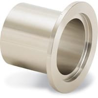
KF (QF) HV Half Nipples (Aluminum 6061-T6) are essential components for users seeking lightweight, corrosion-resistant fittings in high-vacuum (HV) systems. These half nipples are specifically designed with a single KF (QF) flange, offering a simple yet versatile solution for connecting tubing or custom components to standard vacuum hardware.

Unlike full nipples with two flanged ends, KF (QF) HV Half Nipples (Aluminum 6061-T6) are ideal for applications where only one side requires a vacuum flange—such as port terminations, foreline extensions, or direct connections to welded tubing assemblies. The open end allows for flexible integration through welding, brazing, or mechanical coupling, while the KF flange ensures compatibility with quick-clamp hardware for fast, tool-free installation.

Crafted from aluminum alloy 6061-T6, these half nipples offer excellent strength-to-weight ratio and thermal conductivity. Their resistance to corrosion and oxidation, combined with ease of machining, makes them particularly suitable for applications in non-corrosive or inert gas environments. Whether used in experimental vacuum setups, optical instrument chambers, or lightweight vacuum frame systems, these components contribute to reduced system mass without compromising vacuum integrity.

As part of TFM’s commitment to vacuum system performance, each KF (QF) HV Half Nipple (Aluminum 6061-T6) is precision-fabricated using vacuum-rated tubing and flanges. The clean internal finish ensures minimal outgassing and particulate generation, supporting vacuum conditions down to 10⁻⁶ Torr or lower, depending on the assembly.

Standard sizes and lengths are available to meet common system requirements, but TFM also provides customization options for users with unique dimensional or performance needs. Whether you need a special tube diameter, custom length, or modified flange design, our engineering team can deliver a tailored solution for your high-vacuum system.

In summary, KF (QF) HV Half Nipples (Aluminum 6061-T6) are a smart choice for engineers and technicians seeking lightweight, adaptable fittings for high-vacuum infrastructure. Their durability, compatibility, and ease of integration make them a staple in both permanent and modular vacuum system designs.

Ordering Table

Flange Size/OD Type Flange Material Part Number
KF10 (1.18" OD) Half Nipple, Clamp Style 316L SS QF10-055-LF
KF16 (1.18" OD) Half Nipple, Clamp Style 316L SS QF16-079-LF
KF25 (1.57" OD) Half Nipple, Clamp Style 316L SS QF25-110-LF
KF40 (2.16" OD) Half Nipple, Clamp Style 316L SS QF40-175-LFL
KF50 (2.95" OD) Half Nipple, Clamp Style 316L SS QF50-224-LF

Accessories Table

Description For Per Package Part Number
Cast Clamps (SS) KF10, KF16 Flanges 1 QF16-075-CS
Cast Clamps (SS) KF25 Flanges 1 QF25-100-CS
Cast Clamps (SS) KF40 Flanges 1 QF40-150-CS
Cast Clamps (SS) KF50 Flanges 1 QF50-200-CS
Cast Clamps (Aluminum) KF10, KF16 Flanges 1 QF16-075-C
Cast Clamps (Aluminum) KF25 Flanges 1 QF25-100-C
Cast Clamps (Aluminum) KF40 Flanges 1 QF40-150-C
Cast Clamps (Aluminum) KF50 Flanges 1 QF50-200-C
Lever Clamps (Aluminum) KF10, KF16 Flanges 1 QF16-075-CHA
Lever Clamps (Aluminum) KF25 Flanges 1 QF25-100-CHA
Lever Clamps (Aluminum) KF40 Flanges 1 QF40-150-CHA
Centering Ring (SS with Fluorocarbon O-Ring) KF10 Flanges 1 QF10-050-SRV
Centering Ring (SS with Fluorocarbon O-Ring) KF16 Flanges 1 QF16-075-SRV
Centering Ring (SS with Fluorocarbon O-Ring) KF25 Flanges 1 QF25-100-SRV
Centering Ring (SS with Fluorocarbon O-Ring) KF40 Flanges 1 QF40-150-SRV
Centering Ring (SS with Fluorocarbon O-Ring) KF50 Flanges 1 QF50-200-SRV

Reviews

There are no reviews yet.

Be the first to review “KF (QF) HV Half Nipples (Aluminum 6061-T6)”

Your email address will not be published. Required fields are marked *

FAQ

Tube fittings are designed for tubes (measured by outside diameter and wall thickness) used in high-pressure and instrumentation applications, whereas pipe fittings are for pipes (identified by nominal pipe size) primarily used in fluid transport.


Common valve types include ball valves, gate valves, check valves, butterfly valves, and globe valves. Each serves a specific function—from quick shutoff (ball/gate valves) to flow regulation (globe valves).

 
  • For tubing, measure the outside diameter; for pipes, refer to the nominal pipe size (using conversion charts if needed). Always match the valve or fitting size to your pipe’s dimensions and flow requirements.

  • Frequently used thread types include NPT (National Pipe Tapered), BSP (British Standard Pipe), and UNC, along with slip-fit options that rely on compression or fusion rather than threads.

Interchangeability depends on manufacturer specifications and certification. Always verify compatibility via manufacturer guides or certified interchangeability charts.

 
  • A coupling is a short, straight fitting used to join two pipes or tubes. It provides a secure, leak-tight connection and can sometimes serve to extend or repair piping runs.

Consider valve type, pressure and temperature ratings, material compatibility with your fluid, actuation method (manual or automatic), and maintenance requirements.

 
  • Valves regulate flow by opening, closing, or partially obstructing the pathway. Their mechanisms (such as the rotation of a ball or the linear movement of a gate) determine the speed and precision of flow control.

  • A flange is a flat, circular component used to connect pipes, valves, or other equipment. Bolted together with gaskets, flanges provide a secure, leak-proof joint that facilitates both assembly and maintenance.

  • Manual valves require physical operation via handles or levers, whereas actuated valves use mechanisms—pneumatic, electric, or hydraulic—to open and close automatically or remotely.

  • Issues include leaks caused by improper installation, over-tightening, degraded seals, material incompatibility, and fatigue from repeated cycling. Regular inspection and proper installation practices help mitigate these problems.

Regular maintenance involves periodic inspections, cleaning or replacing worn seals, ensuring proper torque during installation, and adhering to manufacturer guidelines and local plumbing codes to preserve system integrity.


Shopping Cart
Scroll to Top