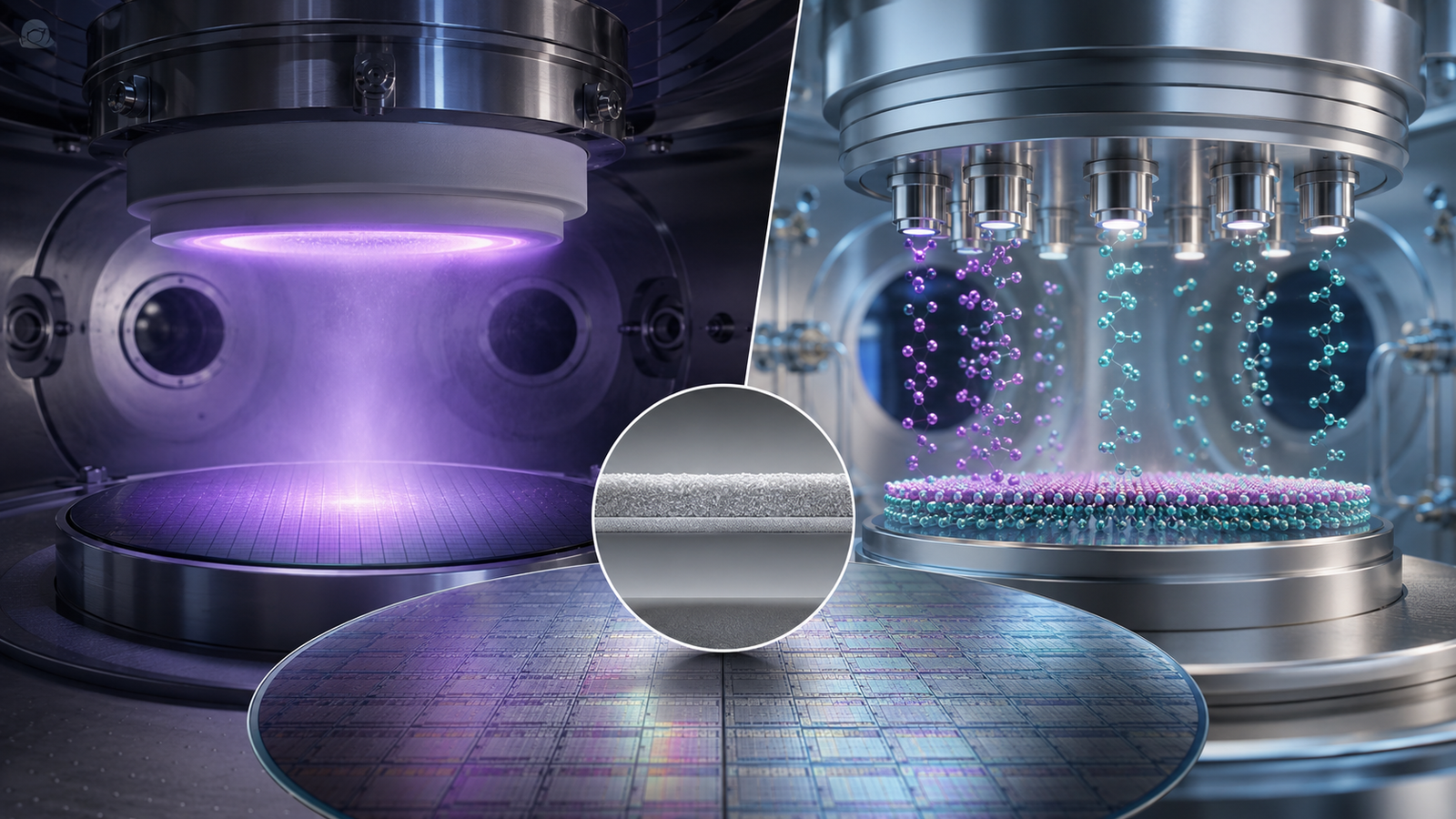
Introduction
In the field of vacuum engineering, the choice of flange connection is a foundational decision that can directly affect the performance, reliability, and longevity of a vacuum system. Among the many types of vacuum flange standards, KF/QF and CF flanges are the most widely adopted. KF (Klein Flange or Quick Flange) is standardized under ISO and is favored for its ease of use in low to medium vacuum environments. CF (ConFlat) flanges, on the other hand, are widely adopted in ultra-high vacuum (UHV) systems due to their exceptional sealing capabilities and high-temperature resilience.
This comprehensive article delves into the technical distinctions between KF/QF and CF flanges, providing engineers, researchers, and vacuum system designers with deep insights into their structural differences, sealing mechanisms, installation requirements, and application environments. By understanding these nuances, users can make informed decisions on component selection for laboratory setups, industrial processes, and scientific experiments. All insights are grounded in TFM’s extensive experience in manufacturing vacuum components for thin film deposition, semiconductor production, and analytical instrumentation.
1. Understanding Vacuum Flanges and Their Importance
Vacuum flanges are essential components in any vacuum system, serving as connection interfaces between tubes, chambers, and instrumentation. A vacuum flange must fulfill several functions:
- Create and maintain a leak-tight seal under vacuum conditions.
- Allow for modular and flexible design.
- Withstand mechanical stress and thermal cycling.
- Enable reliable disassembly and reassembly for maintenance or component replacement.
Selecting the appropriate flange type involves balancing operational pressure range, thermal conditions, material compatibility, ease of assembly, and long-term reliability.
1.1 Classification of Vacuum Flange Systems
- KF/QF Flanges (ISO-KF): Used predominantly in systems where convenience and rapid assembly/disassembly are priorities.
- CF Flanges (ConFlat): Engineered for ultra-high vacuum systems requiring leak rates below 10⁻¹⁰ mbar·L/s.
- ISO Large Flanges (ISO-F): For large-diameter systems, often found in industrial processing.
- ANSI and Custom Flanges: Used in specialized industrial or national-standard systems.
2. KF/QF Flange System: Design and Utility
2.1 Mechanical Structure and Standards
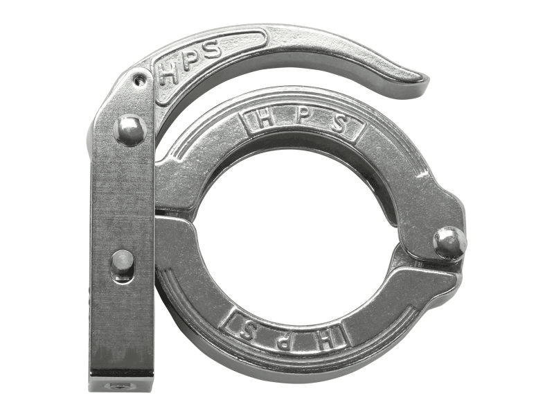
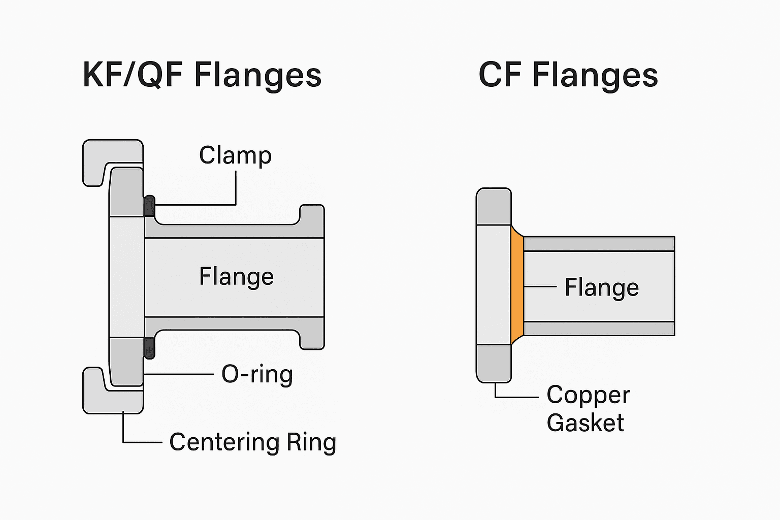
The KF flange system consists of several standardized components:
- KF Flange: A beveled, rotatable collar typically made from 304L stainless steel or aluminum.
- Centering Ring: Houses the elastomeric O-ring and maintains alignment.
- O-ring: Usually made of Viton or Buna-N, providing the primary vacuum seal.
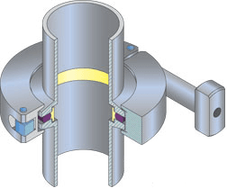
- Clamping Mechanism: A wing-nut or quick-release clamp that provides uniform compression.
ISO-KF flanges are available in sizes ranging from KF10 to KF50 (the number indicates the approximate tube ID in millimeters). These are defined under ISO 2861 and ISO 1609 standards.
2.2 Connection and Sealing Principle
When a KF flange is mated, the centering ring with an O-ring is sandwiched between the flange faces. The clamp applies even force to compress the O-ring slightly, creating a radial seal. This sealing mechanism is simple yet effective for vacuums down to 10⁻⁷ Torr.
2.3 Performance Characteristics
- Pressure Range: From atmospheric pressure down to 10⁻⁷ Torr.
- Temperature Limit: Up to ~150°C for Viton O-rings (up to ~200°C with special compounds).
- Vacuum Leak Rate: Typically <10⁻⁹ mbar·L/s.
2.4 Advantages of KF Flanges
- Quick Assembly and Disassembly: Useful in laboratory and test environments.
- Minimal Tool Requirement: Most assemblies require no tools.
- Cost Efficiency: Ideal for budget-sensitive projects.
- Reusability: O-rings can be reused with proper cleaning.
2.5 Limitations of KF Flanges
- Outgassing: O-rings can outgas, affecting UHV compatibility.
- Chemical Compatibility: Elastomers can degrade in corrosive or plasma-rich environments.
- Thermal Sensitivity: Not suitable for high-temperature bake-outs.
3. CF Flange System: Engineering for UHV
3.1 Design Philosophy
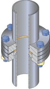
CF flanges are engineered for high-integrity sealing in extreme environments:
- Knife-Edge Design: The flange features a precision-machined knife-edge that cuts into a soft metal gasket (usually OFHC copper).
- Rigid Flange Face: Ensures reliable mating and seal geometry.
- Non-Rotatable or Rotatable Options: Available for fixed or adjustable alignment.
Standard CF flange sizes range from CF16 to CF250 and conform to the ASTM E2734/E2734M and ISO 3669 standards.
3.2 Sealing Mechanism
The metal-to-metal seal is created by compressing the gasket between two flanges, where the knife-edge bites into the gasket. This seal is permanent and capable of sustaining vacuums below 10⁻¹¹ Torr. The mechanical strength ensures minimal leak risk even under thermal cycling and mechanical stress.
3.3 Performance Metrics
- Pressure Range: Down to <10⁻¹¹ Torr.
- Temperature Resistance: Up to 450°C (copper gasket), and 650°C with silver-plated or annealed gaskets.
- Leak Rate: As low as 10⁻¹³ mbar·L/s.
3.4 Advantages of CF Flanges
- Superior Sealing Integrity: Perfect for UHV systems.
- High-Temperature Compatibility: Enables system bake-out.
- Material Stability: All-metal seals are chemically inert.
- Long-Term Reliability: Preferred in scientific apparatus and critical systems.
3.5 Limitations of CF Flanges
- Complex Assembly: Requires torque-controlled tools and careful gasket handling.
- Non-Reusable Gaskets: Copper gaskets must be replaced after each use.
- Higher Cost: Due to precise machining and sealing performance.
4. Technical Comparison: KF vs CF
| Feature | KF/QF Flange | CF Flange |
|---|---|---|
| Vacuum Capability | 10⁻⁷ Torr | 10⁻¹¹ Torr |
| Seal Type | Elastomer (O-ring) | Metal Gasket (Copper) |
| Assembly Time | <1 minute | 10–30 minutes |
| Tool Requirement | No | Torque wrench required |
| Bake-Out Temperature | ~150°C | 450°C and above |
| Maintenance | Frequent O-ring inspection | Gasket replacement required |
| Reusability | Moderate | Low (gasket single-use) |
| Application Flexibility | High (lab setups) | High (UHV, long-term) |
5. Application Scenarios in Industry
5.1 Thin Film Deposition Systems
- KF Flanges: Used in foreline vacuum lines, pumping manifolds, and rough vacuum gauges.
- CF Flanges: Essential in process chambers for sputtering, MBE, or ALD that operate under UHV conditions.
5.2 Semiconductor Fabrication
- KF Flanges: For gas inlet lines, exhaust systems.
- CF Flanges: In etching and lithography tools requiring minimal contamination and absolute sealing.
5.3 Research Laboratories
- KF Flanges: Modular test setups, sample holders, leak test rigs.
- CF Flanges: Particle accelerators, synchrotrons, XPS/UPS systems.
5.4 Space Simulation and Plasma Systems
- CF Flanges: Ideal for vacuum chambers simulating interplanetary space or hosting RF plasma sources.
5.5 Battery and Energy Research
- KF Flanges: Easy integration in glovebox transitions.
- CF Flanges: Electrochemical and material analysis under strict vacuum conditions.
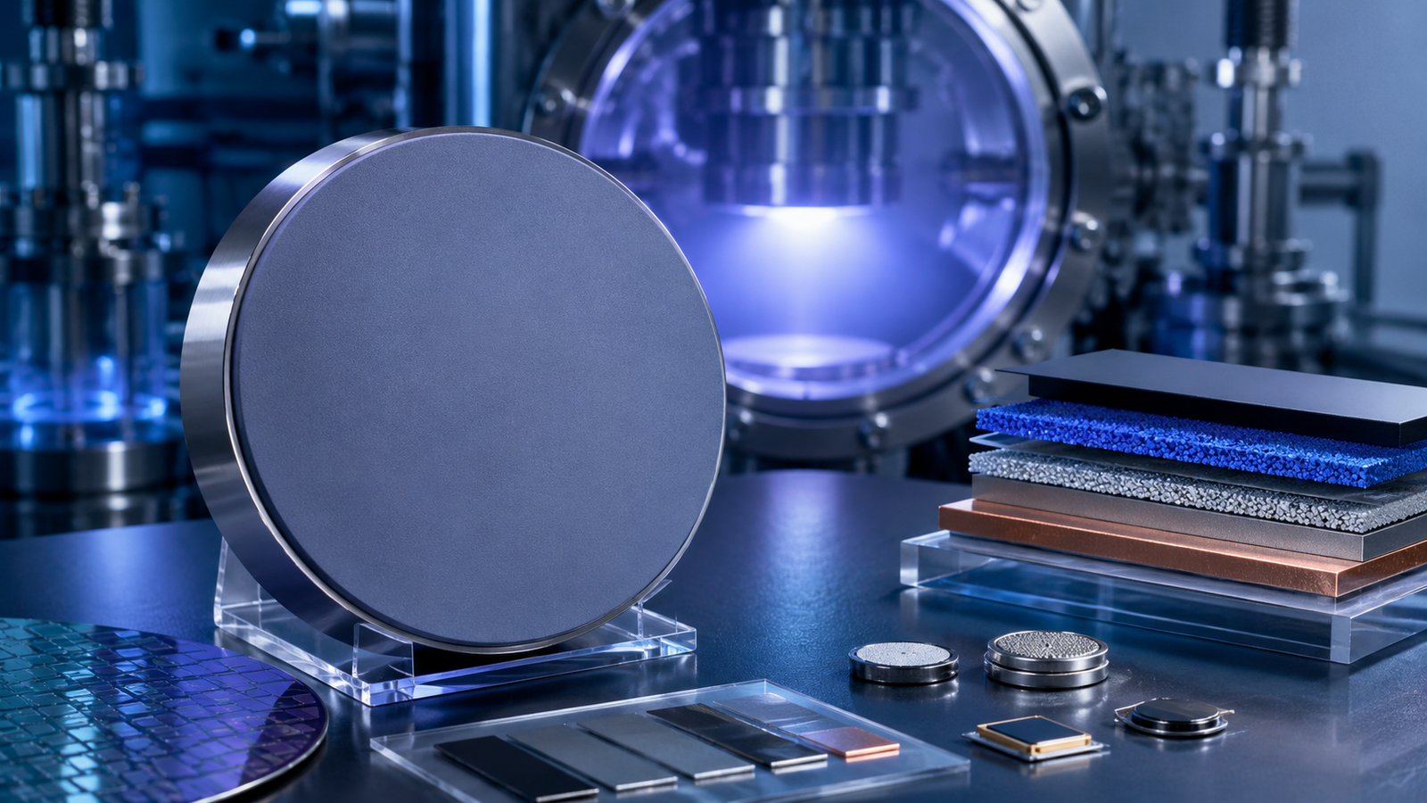
6. TFM’s Vacuum Flange Solutions
TFM (Thin Film Materials) offers a comprehensive catalog of high-performance KF and CF flanges:
- Materials: 304L, 316L stainless steel; aluminum for KF; OFHC copper for CF gaskets.
- Options: Viewports, elbows, tees, crosses, and custom reducer flanges.
- Precision: CNC machined with vacuum-tight welds and surface finishing.
- Customization: Non-standard sizes, rotatable flanges, and specialty coatings available.
TFM’s flanges are leak-tested, cleanroom packaged, and ready for high-purity integration in your vacuum systems. Whether you’re building a compact lab rig or scaling up a production-grade chamber, TFM delivers reliable vacuum sealing solutions tailored to your exact requirements.
7. Maintenance and Best Practices
7.1 KF Flange Handling Tips
- Always inspect O-rings for cracks, flat spots, or contamination.
- Use compatible lubricants (e.g., silicone grease) sparingly.
- Avoid overtightening clamps to preserve O-ring elasticity.
7.2 CF Flange Installation Protocols
- Use a calibrated torque wrench and tighten in a cross-pattern.
- Degrease copper gaskets with acetone before installation.
- Never reuse copper gaskets for critical UHV systems.
8. Conclusion
KF/QF and CF flanges each serve indispensable roles in vacuum systems. KF flanges prioritize speed and flexibility, making them indispensable in R&D and low-vacuum systems. CF flanges, by contrast, represent the gold standard for UHV performance, delivering unmatched sealing integrity and thermal resilience.
Understanding the mechanical and operational nuances between these two flange types is essential for designing vacuum systems that are not only efficient but also robust and reliable over time. TFM is your trusted partner for precision-engineered vacuum components, offering both standard and customized KF and CF solutions to meet the evolving demands of advanced research and industrial applications.
Frequently Asked Questions (FAQs)
1. What is the primary difference between KF/QF and CF flanges?
KF/QF flanges use elastomer O-rings for quick and convenient seals in low-to-medium vacuum applications, while CF flanges utilize copper gaskets for ultra-high vacuum (UHV) environments and offer superior sealing integrity.
2. Which vacuum range is suitable for KF flanges and which for CF flanges?
KF flanges are ideal for systems operating down to 10⁻⁷ Torr. CF flanges are designed for extreme UHV systems reaching pressures as low as 10⁻¹¹ Torr or lower.
3. Can KF and CF flanges be connected directly to each other?
No, they are based on different standards and sealing mechanisms. However, TFM offers adapter flanges that allow interface between KF and CF systems when needed.
4. Are KF flange O-rings reusable?
Yes, O-rings can be reused if they are clean, undamaged, and still elastic. However, they should be inspected regularly for cracks, flattening, or contamination.
5. Why are CF flange gaskets not reusable?
CF flanges use soft metal gaskets that undergo permanent deformation by the knife-edge seal during compression. Reusing them risks leaks and system contamination.
6. What materials are typically used for KF and CF flange components?
KF flange bodies are commonly made of stainless steel (304L or 316L) or aluminum, with O-rings of Viton or Buna-N. CF flanges are made of stainless steel, using oxygen-free high-conductivity (OFHC) copper for the gaskets.
7. Can CF flanges withstand high temperatures?
Yes. CF flanges can handle bake-out temperatures up to 450°C (copper gasket) and higher with silver-plated gaskets. KF flanges are limited to around 150–200°C due to O-ring material constraints.
8. Which flange type is more suitable for frequent disassembly?
KF flanges are much faster and easier to assemble and disassemble without tools, making them ideal for temporary setups, maintenance, or testing environments.
9. What tools are required to install CF flanges properly?
A calibrated torque wrench is needed to tighten CF flange bolts in a cross-pattern sequence. This ensures uniform pressure and a reliable vacuum seal.
10. Where does TFM recommend using KF vs CF flanges in system design?
TFM recommends KF flanges for foreline connections, low-vacuum gauges, and laboratory setups requiring flexibility. CF flanges are preferred in high-precision, long-term vacuum environments such as deposition chambers, UHV analysis instruments, and space simulation systems.