KF (QF) HV Full Nipples (304L SS): Dual-Flanged Stainless Steel Connectors for High-Vacuum Line Integrity
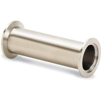
KF (QF) HV Full Nipples (304L SS) are precision-engineered vacuum components featuring two KF (QF) flanges connected by a straight section of 304L stainless steel tubing. These full nipples are ideal for connecting vacuum lines, extending chamber ports, or linking instruments in high-vacuum (HV) systems where leak-tight, corrosion-resistant, and modular construction is critical.
Manufactured by TFM to meet stringent vacuum performance standards, KF (QF) HV Full Nipples (304L SS) are widely used in through-line or foreline plumbing applications and serve as essential structural elements in vacuum chambers, pump stations, and analytical equipment. Their full-flange design enables rapid installation or removal between mating KF flanges using elastomeric o-rings, centering rings, and circumferential clamps.
The use of 304L stainless steel provides superior resistance to corrosion, chemical exposure, and thermal cycling—key characteristics for HV environments subjected to frequent venting, reactive gas flows, or elevated temperatures. The low carbon content of 304L ensures minimal risk of intergranular corrosion, even after welding or prolonged system operation. These properties make KF (QF) HV Full Nipples (304L SS) ideal for cleanroom, semiconductor, thin-film deposition, and R&D vacuum applications.
Each KF (QF) HV Full Nipple (304L SS) is supplied with two KF-standard flanges (e.g., KF16, KF25, KF40, KF50), allowing tool-free integration with existing KF hardware. The tube between the flanges is welded, seamless, and cut to standard or custom-specified lengths, enabling direct integration between vacuum pumps, valves, or diagnostic ports without the need for additional adapters or fittings.
The connection system is simple yet effective: each end of the full nipple is clamped to another KF flange using a centering ring with an o-ring, which is compressed between two chamfered sealing faces. The resulting seal supports vacuum levels down to 10⁻⁸ Torr, with temperature limits governed by the o-ring material—typically in the range of 0 °C to 120–180 °C.
TFM offers KF (QF) HV Full Nipples (304L SS) in a variety of standard lengths and flange sizes to suit common vacuum system architectures. For specific design needs, custom fabrication is available, including non-standard lengths, vented tube options, and precision internal surface finishes (e.g., electropolishing) for ultra-clean applications.
In summary, KF (QF) HV Full Nipples (304L SS) deliver robust, vacuum-compatible connectivity for critical HV system segments. With dual KF flanges, corrosion-resistant stainless steel tubing, and seamless compatibility with KF hardware, these nipples are a cornerstone component in building high-performance, modular vacuum environments.
Ordering Table
| Flange Size/OD | Type | Flange Material | Drawing | Part Number |
| KF16 (1.18" OD) | Full Nipple, Clamp Style | 304L SS |

| QF16-075-N |
| KF16 (1.18" OD) | Full Nipple, Clamp Style | 304L SS |

| QF16-075-NL |
| KF25 (1.57" OD) | Full Nipple, Clamp Style | 304L SS |

| QF25-100-N |
| KF25 (1.57" OD) | Full Nipple, Clamp Style | 304L SS |

| QF25-100-NL |
| KF40 (2.16" OD) | Full Nipple, Clamp Style | 304L SS |
| QF40-150-N |
| KF40 (2.16" OD) | Full Nipple, Clamp Style | 304L SS |

| QF40-150-NL |
| KF50 (2.95" OD) | Full Nipple, Clamp Style | 304L SS |

| QF50-200-N |
| KF50 (2.95" OD) | Full Nipple, Clamp Style | 304L SS |

| QF50-200-NL |
Accessories Table
| Description | For | Per Package | Part Number |
| Cast Clamps (SS) | KF10, KF16 Flanges | 1 | QF16-075-CS |
| Cast Clamps (SS) | KF25 Flanges | 1 | QF25-100-CS |
| Cast Clamps (SS) | KF40 Flanges | 1 | QF40-150-CS |
| Cast Clamps (SS) | KF50 Flanges | 1 | QF50-200-CS |
| Cast Clamps (Aluminum) | KF10, KF16 Flanges | 1 | QF16-075-C |
| Cast Clamps (Aluminum) | KF25 Flanges | 1 | QF25-100-C |
| Cast Clamps (Aluminum) | KF40 Flanges | 1 | QF40-150-C |
| Cast Clamps (Aluminum) | KF50 Flanges | 1 | QF50-200-C |
| Lever Clamps (Aluminum) | KF10, KF16 Flanges | 1 | QF16-075-CHA |
| Lever Clamps (Aluminum) | KF25 Flanges | 1 | QF25-100-CHA |
| Lever Clamps (Aluminum) | KF40 Flanges | 1 | QF40-150-CHA |
| Centering Ring (SS with Fluorocarbon O-Ring) | KF10 Flanges | 1 | QF10-050-SRV |
| Centering Ring (SS with Fluorocarbon O-Ring) | KF16 Flanges | 1 | QF16-075-SRV |
| Centering Ring (SS with Fluorocarbon O-Ring) | KF25 Flanges | 1 | QF25-100-SRV |
| Centering Ring (SS with Fluorocarbon O-Ring) | KF40 Flanges | 1 | QF40-150-SRV |
| Centering Ring (SS with Fluorocarbon O-Ring) | KF50 Flanges | 1 | QF50-200-SRV |
| Description | For | Per Package | Part Number |


Reviews
There are no reviews yet.