Introduction
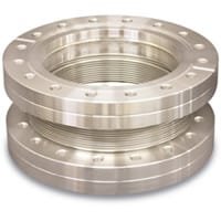
Flex Metal Edge-Welded Bellows with ConFlat (CF) Flanges are critical components in ultra-high vacuum (UHV) and high-purity process systems. They are designed to provide precise axial, lateral, and angular flexibility while maintaining absolute vacuum integrity. By combining edge-welded bellows construction with knife-edge CF flanges, these assemblies deliver reliable motion compensation, vibration isolation, and thermal expansion absorption in demanding scientific and industrial environments.
Detailed Description
Edge-welded metal bellows are manufactured by welding together thin metal diaphragms at their edges, forming a flexible yet hermetically sealed structure. Compared with formed bellows, edge-welded bellows offer lower spring rates, higher flexibility, and superior fatigue life, making them ideal for applications requiring frequent or precise motion.
The integration of ConFlat (CF) flanges ensures metal-to-metal sealing using OFHC copper gaskets. This design eliminates elastomers, enabling operation in UHV conditions down to 10⁻⁹ mbar and compatibility with high-temperature bake-out processes. Common materials include 304L or 316L stainless steel for excellent corrosion resistance, weldability, and mechanical stability under vacuum.
These bellows assemblies can be configured for axial compression/extension, lateral offset, or angular deflection. Wall thickness, convolution count, and overall length are optimized to balance flexibility with pressure resistance and cycle life. Custom options are available to match specific vacuum system layouts and motion requirements.
Applications
Flex Metal Edge-Welded Bellows with CF Flanges are widely used in:
Ultra-high vacuum (UHV) and high-vacuum systems
Semiconductor fabrication and wafer processing equipment
Thin-film deposition systems (PVD, CVD, ALD)
Particle accelerators and beamline systems
Synchrotron radiation and research laboratories
Vacuum valves, motion feedthroughs, and alignment stages
Thermal expansion compensation in rigid vacuum piping
Technical Parameters
| Parameter | Typical Value / Range | Importance |
|---|---|---|
| Material | 304L / 316L Stainless Steel | Ensures corrosion resistance and vacuum compatibility |
| Flange Type | CF16 – CF250 (custom sizes) | Matches UHV standard connections |
| Leak Rate | ≤ 1 × 10⁻¹⁰ mbar·L/s | Guarantees vacuum integrity |
| Operating Pressure | Vacuum to atmosphere | Suitable for vacuum isolation and compensation |
| Temperature | Up to 450 °C (bake-out) | Supports UHV bake-out procedures |
| Cycle Life | 10⁵ – 10⁶ cycles (design-dependent) | Ensures long-term reliability |
Comparison with Related Bellows Types
| Bellows Type | Key Advantage | Typical Application |
|---|---|---|
| Flex Metal Edge-Welded Bellows with CF Flanges | High flexibility, UHV compatible | Semiconductor & research vacuum systems |
| Formed Metal Bellows | Lower cost, higher pressure tolerance | Industrial piping |
| Elastomer Bellows | Simple design | Low-vacuum or non-critical systems |
FAQ
| Question | Answer |
|---|---|
| Can the bellows length and flexibility be customized? | Yes. Length, convolution count, and spring rate can be tailored. |
| Are these bellows suitable for UHV systems? | Yes, CF flanges and edge-welded construction support UHV conditions. |
| What gasket is used with CF flanges? | Standard OFHC copper gaskets are recommended. |
| Can other alloys be supplied? | Nickel-based or specialty alloys are available upon request. |
| How are the bellows tested? | Each assembly can be helium leak tested before delivery. |
Packaging
Our Flex Metal Edge-Welded Bellows with CF Flanges are individually cleaned, capped, and vacuum-sealed to prevent contamination. Each unit is clearly labeled for traceability and protected with shock-absorbing materials to ensure safe transportation and storage.
Conclusion
Flex Metal Edge-Welded Bellows with ConFlat (CF) Flanges provide a dependable solution for motion compensation and vibration isolation in ultra-high vacuum systems. Their combination of precision flexibility, metal-sealed reliability, and customization options makes them a preferred choice for advanced research and semiconductor applications.
For detailed specifications and a quotation, please contact us at sales@thinfilmmaterials.com.
Ordering Table
| Drawing | FlangeSize | BellowsOD | BellowsID | Part Number |

| 1-1/3" | 0.75 | 0.25 | MEW0750251C1 |

| 1-1/3" | 1.03 | 0.55 | MEW1030551C2 |

| 1-1/3" | 1.03 | 0.55 | MEW1030551C3 |
|
| 2-3/4" | 1.5 | 0.96 | MEW1500961C1 |
|
| 2-3/4" | 1.89 | 1.39 | MEW1891391C2 |
|
| 2-3/4" | 1.89 | 1.39 | MEW1891391C3 |

| 3-3/8" | 2 | 1.25 | MEW2001251C1 |
|
| 2-3/4" | 2.25 | 1.5 | MEW2251501C2 |
|
| 2-3/4" | 2.25 | 1.5 | MEW2251501C3 |
|
| 4-1/2" | 2.75 | 1.75 | MEW2751751C1 |
|
| 3-3/8" | 3 | 2 | MEW3002001C2 |
|
| 3-3/8" | 3 | 2 | MEW3002001C3 |
|
| 4-1/2" | 3.5 | 2.5 | MEW3502501C2 |
|
| 4-1/2" | 3.5 | 2.5 | MEW3502501C3 |
|
| 6" | 4.97 | 4 | MEW4974001C3 |
|
| 8" | 7.5 | 6 | MEW7506001C3 |
|
| 10" | 9.8 | 8.8 | MEW9508501C3 |
Accessories Table
| Description | For | Per Package | Manual | VacuCADSM | Part Number |
| Gasket, Copper, DN16CF (1.33" OD) Flange , 0.837" OD, 0.640" ID, (10) Per Package | 1-1/3" (DN16CF) Flanges | 10 | — | N/A | GA-0133 |
| Gasket, Copper, DN35CF-DN40CF (2.75" OD) Flange, 1.895" OD, 1.451" ID, (10) Per Package | 2-3/4" (DN35-DN40CF) Flanges | 10 | — | N/A | GA-0275 |
| Gasket, Copper, DN50CF (3.375" OD) Flange, 2.425" OD, 2.010" ID, (10) Per Package | 3-3/8" (DN50CF) Flanges | 10 | — | N/A | GA-0337 |
| Gasket, Copper, DN63CF (4.50" OD) Flange, 3.243" OD, 2.506" ID, (10) Per Package | 4-1/2" (DN63CF) Flanges | 10 | — | N/A | GA-0450 |
| Gasket, Copper, DN100CF (6.00" OD) Flange, 4.743" OD,4.006" ID, (10) Per Package | 6" (DN100CF) Flanges | 10 | — | N/A | GA-0600 |
| Gasket, Copper, DN160CF (8.00" OD) Flange, 6.743" OD, 6.007" ID, (10) Per Package | 8" (DN160CF) Flanges | 10 | — | N/A | GA-0800 |
| Gasket, Copper, DN200CF (10.00" OD) Flange, 8.743" OD, 8.007" ID, (10) Per Package | 10" (DN200CF) Flanges | 10 | — | N/A | GA-1000 |
| Thread Lubricant, 4 Ounce Tube | All CF Flanges | 1 | — | N/A | VZTL-4OZ |
| Gasket Removal Tool, For All Conflat (CF) Flange Sizes | All CF Flanges | 1 | — | N/A | VZGRT |
| Gasket Clips, For All Conflat (CF) Flange Sizes, (10) Per Package | All CF Flanges | 10 | N/A | VGC0275S |

Reviews
There are no reviews yet.