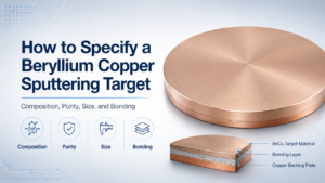
A sputtering target does not need a backing plate simply because it is ceramic, thin, large, or operated above one fixed power value. Bonding is an assembly decision. The correct configuration depends on the target material, dimensions, brittleness, cathode interface, cooling path, bond material, operating temperature, power ramp, and inspection requirements.
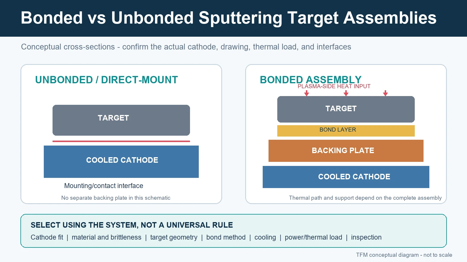
An unbonded target can be appropriate when a compatible cathode provides the required mounting and thermal contact. A bonded target can provide a defined target-to-backing interface, mechanical support, and a thermal path to the cooled cathode. Neither configuration is universally superior, and neither guarantees film performance.
For available material families, start with the Sputtering Targets catalog. If target geometry is still being selected, compare planar and rotatable sputtering targets before defining the assembly.
Bonded vs unbonded sputtering targets: quick comparison
| Selection factor | Unbonded target | Bonded target assembly |
|---|---|---|
| Basic construction | Target mounts directly against or into a compatible cathode interface | Target joins to a backing plate or carrier through a defined bond or joining process |
| Thermal path | Depends on direct contact, clamping, interface condition, target thickness, and cathode cooling | Includes target, bond layer, backing plate or carrier, and cathode cooling interfaces |
| Mechanical support | Provided by the target geometry and cathode mounting arrangement | Backing or carrier can support a thin, brittle, segmented, or otherwise assembly-dependent target |
| Main risks | Poor contact, local heating, movement, incorrect clamp load, or incompatible geometry | Voids, incomplete wetting, debonding, solder or adhesive limits, thermal-expansion mismatch, or backing distortion |
| Quotation input | Target drawing plus cathode interface and operating context | Complete target, bond, backing/carrier, cathode, thermal, and inspection requirements |
What the backing plate and bond actually do
A backing plate or carrier can serve several functions: locate the target in the cathode, transmit clamping or mounting loads, support a target that cannot carry those loads alone, and conduct heat toward the cooling system. The bond layer connects the target to that support. Its thermal conductivity, thickness, coverage, wetting, compliance, and temperature limit all affect the assembly.
Published heat-transfer and stress analyses show why the full stack matters. A locally poor interface can create a different temperature field from a uniform interface, while thermal-expansion mismatch can load the target, bond, and backing during bonding, cooldown, sputtering, and power cycling. These are system-dependent engineering problems; they cannot be resolved from a material name alone.
When an unbonded target may be suitable
- The cathode is designed and qualified for direct mounting of the target geometry.
- The target has adequate mechanical integrity for the specified clamp, support, and handling method.
- The direct-contact interface provides an acceptable thermal path under the intended operating window.
- The target thickness and total installed height remain within cathode limits.
- The process team has a qualified installation, conditioning, cooling, and inspection procedure.
Metallic targets are often candidates for direct mounting, but “metal” is not a sufficient specification. A thin or soft target can deform; a large target can have contact or flatness constraints; a high thermal load can expose weaknesses in the interface. The installed cathode and the complete drawing remain decisive.
When a bonded assembly deserves evaluation
- The cathode requires a backing plate, carrier tube, keeper, or another defined mounting interface.
- The target is brittle, thin, segmented, unusually shaped, or otherwise needs support.
- The process needs a controlled thermal path from target to cooled cathode.
- The approved replacement assembly already defines a backing and bond system.
- Bond coverage, backing reuse, or assembly inspection is part of the acceptance plan.
Ceramic targets frequently receive backing support because they may be brittle and sensitive to thermal gradients, but the decision still depends on material, diameter or length, thickness, cathode design, cooling, and operating conditions. A universal rule such as “all ceramic targets must be bonded” is not technically defensible.
Bonding methods are not interchangeable
Indium and other metallic solder bonds
Indium is used in sputtering-target bonding because it is soft, wets suitably prepared surfaces under an appropriate process, and can accommodate some differential movement. Its low melting point also creates a temperature constraint. The allowable operating window for an assembly must be defined by the complete bond design and supplier guidance rather than inferred from indium’s melting point alone.
Other solder or braze systems use different melting ranges, wetting behavior, interlayers, thermal properties, and processing temperatures. A higher-temperature joining process can itself introduce residual stress or distortion. Selection therefore includes both manufacturing exposure and sputtering exposure.
Elastomeric or adhesive bonds
Filled elastomer or adhesive systems can provide compliance and avoid some high-temperature soldering steps. Their thermal conductivity, vacuum suitability, thickness control, temperature limit, outgassing behavior, and long-term response must be evaluated for the application. “Elastomer bonded” is not a complete acceptance specification.
Diffusion and other solid-state joining routes
Diffusion-bonded assemblies avoid a low-melting solder layer, but require compatible materials, surfaces, pressure, temperature, and process control. Patents for target/backing assemblies describe both the potential thermal advantage and the difficulty of managing distortion, mismatch, and interface quality. Availability and suitability must be reviewed for the specific target and backing pair.
TFM currently provides separate quotation paths for indium target bonding and elastomeric target bonding. Submit the operating and assembly requirements for review rather than selecting a method only by name.
Backing plate selection
Copper and aluminum alloys are common backing materials, but backing selection is not a simple thermal-conductivity ranking. The design must consider cathode compatibility, stiffness, corrosion environment, coolant interface, coefficient of thermal expansion, joining process, reuse plan, total thickness, surface preparation, and dimensional stability.
For a copper route, the OFHC copper backing plate page provides the relevant product path. The final material grade and drawing still need confirmation for each assembly.
Common assembly failure modes
| Observed condition | Possible contributors to investigate | Evidence to collect |
|---|---|---|
| Local hot region | Cooling restriction, poor contact, bond void, interface contamination, unsuitable power ramp, or eroded target geometry | Cooling data, power history, temperature evidence, ultrasonic map if specified, photographs, and cross-section after retirement |
| Debonding or lifted area | Incomplete wetting, contamination, thermal-expansion mismatch, temperature excursion, fatigue, or backing distortion | Bond-process record, thermal history, interface map, flatness, and failure location |
| Target crack | Handling damage, clamp load, residual stress, thermal gradient, unsupported span, arc event, or local bond defect | Crack origin, installation record, ramp sequence, cooling record, target thickness, and assembly drawing |
| Backing plate bow or non-flatness | Joining temperature, material mismatch, asymmetric thickness, machining stress, or repeated reuse | Flatness before/after bonding, material certificates, thickness map, and reuse history |
| Solder movement or extrusion | Temperature beyond the qualified window, excessive bond thickness, orientation, poor containment, or local overheating | Assembly temperature estimate, bond design, operating record, and interface inspection |
These are diagnostic possibilities, not remote failure determinations. A useful investigation combines the target, cathode, cooling, power, gas, maintenance, and inspection records before assigning cause.
Inspection and acceptance requirements
Bond coverage is often evaluated by an agreed nondestructive method such as ultrasonic inspection. Do not assume one universal coverage percentage or void-size limit. The purchase specification should state the inspection method, report format, acceptance threshold, treatment of edge regions, permitted isolated indications, and whether the result applies to the full assembly or a defined bond area.
- Target and backing dimensions, tolerances, and flatness
- Bond method, bond-area definition, and interface preparation
- Inspection method and acceptance criteria
- Material identity and any required composition or impurity report
- Assembly identification, drawing revision, and traceability requirement
- Packing, handling, storage, and installation instructions
RFQ checklist for a bonded or unbonded target
- Target material, formula, alloy or dopant composition, and composition basis
- Purity basis and critical impurity limits
- Target dimensions, tolerances, surface finish, edge details, and quantity
- Cathode or sputtering-gun manufacturer and model
- Direct-mount, backing plate, carrier tube, keeper, or another interface
- Backing/carrier material, dimensions, condition, and reuse requirement
- Requested bond method or permission for engineering review
- Target-only thickness and total installed assembly thickness
- Power mode, intended operating range, duty cycle, and ramp procedure
- Cooling arrangement, coolant conditions, and known temperature limits
- Inspection, documentation, traceability, and acceptance requirements
- Existing approved drawing or retired assembly information for replacements
Send the available drawing and operating context through Contact TFM. If a field is unknown, identify it as unknown so that it can be reviewed instead of silently assumed.
Frequently asked questions
Do all ceramic sputtering targets need bonding?
No universal rule applies. Many ceramic targets benefit from backing support, but the decision depends on the ceramic, dimensions, thickness, cathode, mounting method, cooling, power, and qualified operating procedure.
Is indium bonding suitable for high-power sputtering?
It can be suitable only within the qualified thermal window of the complete assembly. Indium’s low melting point is one constraint, but bond thickness, coverage, cooling, target material, backing, geometry, and local temperature also matter. Do not use a universal power-density limit without system evidence.
Can a backing plate be reused?
Reuse may be possible when the material, dimensions, cooling interfaces, flatness, threads, sealing areas, and remaining condition meet the approved drawing and inspection plan. Reuse should be requested before quotation so removal, cleaning, inspection, and identification can be included.
Technical references
- Society of Vacuum Coaters, Heat Transfer and Stress Analysis of Bonded Sputter Target Assemblies.
- Society of Vacuum Coaters, A Room Temperature, Low-Stress Bonding Process to Reduce the Impact of Use Stress on a Sputtering Target Assembly.
- Society of Vacuum Coaters, Measuring the Performance of Low-Melting Metallic Sputtering Targets Bonded at Room Temperature.
- EP1728892A2: Bonding of sputtering target to target holder, including thermal-expansion and interface considerations.
- US11414745: Sputtering target-backing plate assembly and production method, including solder/braze and diffusion-bonding context.