Introduction
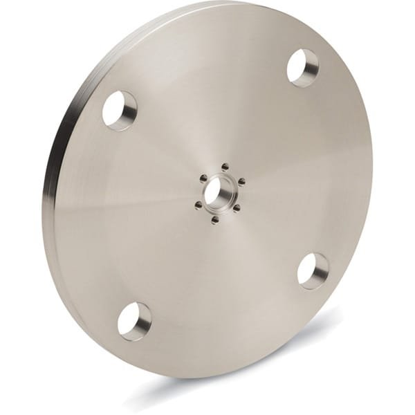
The CF to ASA Nipple—Flat & Grooved is a precision vacuum adapter designed to interface ConFlat (CF) flanges with ASA-style connections. Commonly used in high-vacuum and ultra-high-vacuum (HV/UHV) systems, this nipple provides a reliable, leak-tight transition for research, semiconductor processing, coating systems, and industrial vacuum lines where compatibility and cleanliness are critical.
Detailed Description
This adapter nipple bridges CF knife-edge sealing to ASA connections, enabling flexible system integration without compromising vacuum integrity. Two face options are available to suit different sealing and handling preferences:
Flat Face: Optimized for smooth contact surfaces and straightforward alignment. The flat variant is preferred where minimal turbulence and easy cleaning are priorities.
Grooved Face: Incorporates a precision groove to improve gasket retention and positioning during assembly, reducing installation errors in repetitive or high-throughput setups.
Manufactured from vacuum-grade stainless steel (typically 304L or 316L), each nipple undergoes fine machining and surface finishing to ensure low outgassing, excellent corrosion resistance, and long service life. Dimensional accuracy supports consistent torque application and repeatable sealing performance. Custom lengths, diameters, and surface finishes (e.g., electropolished) are available to match system requirements.
Applications
Semiconductor fabrication tools and load-lock systems
Thin film deposition (PVD/CVD) and sputtering chambers
Research laboratories and analytical instruments
Industrial vacuum furnaces and leak-test rigs
Optical coating and surface science equipment
Technical Parameters
| Parameter | Typical Value / Range | Importance |
|---|---|---|
| Material | 304L / 316L Stainless Steel | Ensures corrosion resistance and low outgassing |
| CF Size | DN16 – DN250 (custom) | Matches standard ConFlat interfaces |
| ASA Size | ASA 1/2″ – 6″ (custom) | Ensures compatibility with ASA systems |
| Face Type | Flat or Grooved | Affects gasket retention and assembly ease |
| Surface Finish | Machined / Electropolished (optional) | Influences cleanliness and outgassing |
| Leak Rate | ≤ 1×10⁻¹⁰ mbar·L/s (typical) | Confirms vacuum integrity |
Comparison with Related Materials
| Material | Key Advantage | Typical Application |
|---|---|---|
| CF to ASA Nipple—Flat & Grooved | Direct CF–ASA compatibility, UHV-ready | Research & semiconductor tools |
| CF to ISO Adapter | Quick clamp convenience | Medium to high vacuum systems |
| All-CF Nipple | Maximum UHV performance | Pure CF vacuum lines |
FAQ
| Question | Answer |
|---|---|
| Can sizes be customized? | Yes. CF/ASA sizes, length, and finish can be tailored. |
| Flat or grooved—which should I choose? | Flat for easy cleaning; grooved for better gasket positioning. |
| Is it suitable for UHV? | Yes, with appropriate material and surface finish. |
| What gaskets are used? | CF side uses copper gaskets; ASA side follows ASA standards. |
| How is it packaged? | Cleaned, capped, and vacuum-sealed for shipment. |
Packaging
Our CF to ASA Nipple—Flat & Grooved products are carefully cleaned, capped, and vacuum-sealed. Each unit is clearly labeled for traceability and protected with foam inserts and export-grade cartons or wooden crates to prevent damage during storage and transportation.
Conclusion
The CF to ASA Nipple—Flat & Grooved delivers dependable sealing, precise fit, and flexible configuration for demanding vacuum environments. With multiple face options and full customization support, it integrates seamlessly into both new builds and retrofit projects.
For detailed specifications and a quotation, please contact us at sales@thinfilmmaterials.com.
Ordering Table
| Flange Size/OD | Type | Drawing | Nominal Tube OD | VacuCADSM | Part Number |
| ASA 1 (4.25" OD) | Grooved |

| 1 | (please log in) | AN0212XAS4G |
| ASA 6 (11.00" OD) | Flat |
| 1-1/2 | (please log in) | AN0275XAS11 |
| ASA 6 (11.00" OD) | Grooved |
| 1-1/2 | (please log in) | AN0275XAS11G |
| ASA 6 (11.00" OD) | Flat |
| 2-1/2 | (please log in) | AN0450XAS11 |
| ASA 8 (13.50" OD) | Grooved |
| 2-1/2 | (please log in) | AN0450XAS13G |
| ASA 10 (16.00" OD) | Flat |
| 2-1/2 | (please log in) | AN0450XAS16 |
| ASA 2 (6.00" OD) | Grooved |
| 2-1/2 | (please log in) | AN0450XAS6G |
| ASA 4 (9.00" OD) | Flat |
| 2-1/2 | (please log in) | AN0450XAS9 |
| ASA 6 (11.00" OD) | Flat |
| 4 | (please log in) | AN0600XAS11 |
| ASA 6 (11.00" OD) | Grooved |
| 4 | (please log in) | AN0600XAS11G |
| ASA 8 (13.50" OD) | Grooved |
| 4 | (please log in) | AN0600XAS13G |
| ASA 10 (16.00" OD) | Grooved |
| 4 | (please log in) | AN0600XAS16G |
| ASA 4 (9.00" OD) | Grooved |
| 4 | (please log in) | AN0600XAS9G |
| ASA 6 (11.00" OD) | Flat |
| 6 | (please log in) | AN0800XAS11 |
| ASA 6 (11.00" OD) | Grooved |
| 6 | (please log in) | AN0800XAS11G |
| ASA 8 (13.50" OD) | Flat |
| 6 | (please log in) | AN0800XAS13 |
| ASA 8 (13.50" OD) | Grooved |
| 6 | (please log in) | AN0800XAS13G |
| ASA 10 (16.00" OD) | Grooved |
| 6 | (please log in) | AN0800XAS16G |
| ASA 8 (13.50" OD) | Flat |
| 8 | (please log in) | AN1000XAS13 |
| ASA 8 (13.50" OD) | Grooved |
| 8 | (please log in) | AN1000XAS13G |
Reviews
There are no reviews yet.