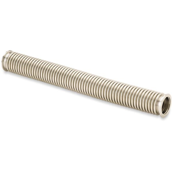
KF Flanged Formed Bellows for HV Systems with Braided Wall
At TFM, we produce high-quality KF flanged formed bellows specifically designed for high vacuum (HV) systems. These bellows are constructed from 300 series stainless steel flexible hoses and equipped with 304L stainless steel KF (QF) flanges. The KF (QF) flanges are used in through-line or foreline vacuum plumbing, as well as for straightforward HV chamber ports, ensuring reliable performance in vacuum environments.
MH-Series Bellows
- Material: Fabricated from thin 300 series stainless steel, these bellows are built to withstand numerous flexing cycles, ensuring durability in demanding applications.
Key Features of KF (QF) Flanged Braided Flexible Hoses:
- Braided Flexible Hoses: Featuring a braided sheath that protects the convoluted hose from potential damage, making these hoses more resilient and suitable for harsh conditions.
- Short Flexible Hoses: These hoses are ideal for fixing minor component misalignments, providing an easy solution for alignment corrections within vacuum systems.
- Longer Flexible Hoses: Commonly utilized as roughing lines, these hoses offer flexibility for applications requiring extended reach while maintaining vacuum integrity.
TFM’s KF flanged bellows with braided walls provide robust protection and flexibility, making them an excellent choice for high-performance HV systems. Whether for minor adjustments or extensive vacuum lines, these bellows are designed to meet a wide range of industrial needs.
Ordering Table
| Drawing | FlangeSize | Length | WallThickness | BellowsID | Part Number |

| 16 | 3 | 0.008 | 0.75 | MHB-QF-A03 |
|
| 16 | 6 | 0.008 | 0.75 | MHB-QF-A06 |
|
| 16 | 10 | 0.008 | 0.75 | MHB-QF-A10 |
|
| 16 | 12 | 0.008 | 0.75 | MHB-QF-A12 |
|
| 16 | 18 | 0.008 | 0.75 | MHB-QF-A18 |
|
| 16 | 20 | 0.008 | 0.75 | MHB-QF-A20 |
|
| 16 | 24 | 0.008 | 0.75 | MHB-QF-A24 |
|
| 16 | 30 | 0.008 | 0.75 | MHB-QF-A30 |
|
| 16 | 36 | 0.008 | 0.75 | MHB-QF-A36 |
|
| 16 | 40 | 0.008 | 0.75 | MHB-QF-A40 |
|
| 16 | 48 | 0.008 | 0.75 | MHB-QF-A48 |
|
| 25 | 3 | 0.008 | 1 | MHB-QF-B03 |
|
| 25 | 6 | 0.008 | 1 | MHB-QF-B06 |
|
| 25 | 10 | 0.008 | 1 | MHB-QF-B10 |
|
| 25 | 12 | 0.008 | 1 | MHB-QF-B12 |
|
| 25 | 18 | 0.008 | 1 | MHB-QF-B18 |
|
| 25 | 20 | 0.008 | 1 | MHB-QF-B20 |
|
| 25 | 24 | 0.008 | 1 | MHB-QF-B24 |
|
| 25 | 30 | 0.008 | 1 | MHB-QF-B30 |
|
| 25 | 36 | 0.008 | 1 | MHB-QF-B36 |
|
| 25 | 40 | 0.008 | 1 | MHB-QF-B40 |
|
| 25 | 48 | 0.008 | 1 | MHB-QF-B48 |
|
| 25 | 80 | 0.008 | 1 | MHB-QF-B80 |
|
| 40 | 3 | 0.010 | 1.5 | MHB-QF-C03 |
|
| 40 | 6 | 0.010 | 1.5 | MHB-QF-C06 |
|
| 40 | 10 | 0.010 | 1.5 | MHB-QF-C10 |
|
| 40 | 12 | 0.010 | 1.5 | MHB-QF-C12 |
|
| 40 | 18 | 0.010 | 1.5 | MHB-QF-C18 |
|
| 40 | 20 | 0.010 | 1.5 | MHB-QF-C20 |
|
| 40 | 24 | 0.010 | 1.5 | MHB-QF-C24 |
|
| 40 | 30 | 0.010 | 1.5 | MHB-QF-C30 |
|
| 40 | 36 | 0.010 | 1.5 | MHB-QF-C36 |
|
| 40 | 40 | 0.010 | 1.5 | MHB-QF-C40 |
|
| 40 | 48 | 0.010 | 1.5 | MHB-QF-C48 |
|
| 50 | 4 | 0.012 | 2 | MHB-QF-D04 |
|
| 50 | 6 | 0.012 | 2 | MHB-QF-D06 |
|
| 50 | 10 | 0.012 | 2 | MHB-QF-D10 |
|
| 50 | 12 | 0.012 | 2 | MHB-QF-D12 |
|
| 50 | 18 | 0.012 | 2 | MHB-QF-D18 |
|
| 50 | 20 | 0.012 | 2 | MHB-QF-D20 |
|
| 50 | 24 | 0.012 | 2 | MHB-QF-D24 |
|
| 50 | 30 | 0.012 | 2 | MHB-QF-D30 |
|
| 50 | 36 | 0.012 | 2 | MHB-QF-D36 |
|
| 50 | 48 | 0.012 | 2 | MHB-QF-D48 |

Reviews
There are no reviews yet.