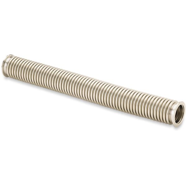
KF Flanged Formed Bellows for HV Systems
TFM manufactures KF flanged formed bellows designed for high vacuum (HV) systems, using 300 series stainless steel flexible hoses paired with 304L stainless steel KF (QF) flanges. The KF (QF) flange is ideal for use in through-line or foreline vacuum plumbing, as well as simple ports in HV chambers, offering a reliable solution for vacuum sealing and connections.
MH-Series Bellows
- Material: Manufactured from thin 300 series stainless steel, these bellows are designed to endure multiple flexing cycles without compromising their durability or flexibility.
Features of KF (QF) Flanged Flexible Hoses:
- Unbraided Flexible Hoses: Capable of extending up to 10% beyond their operational length and compressing up to 15%, providing versatility in various vacuum applications.
- Braided Flexible Hoses: Protected by a braided sheath, these hoses are designed to safeguard the convoluted structure from wear and damage, making them more robust for harsher environments.
- Short Flexible Hoses: Perfect for addressing minor misalignments in components, ensuring proper connections in tight spaces.
- Longer Flexible Hoses: Typically used as roughing lines, these hoses offer flexibility for applications requiring more extensive connections.
TFM’s KF flanged bellows provide a versatile, durable solution for HV systems, designed to meet the needs of both small-scale adjustments and larger vacuum applications.
Ordering Table
| Drawing | FlangeSize | Length | WallThickness | BellowsID | Part Number |

| 16 | 3 | 0.006 | 0.75 | MHT-QF-A03 |
|
| 16 | 6 | 0.006 | 0.75 | MHT-QF-A06 |
|
| 16 | 10 | 0.006 | 0.75 | MHT-QF-A10 |
|
| 16 | 12 | 0.006 | 0.75 | MHT-QF-A12 |
|
| 16 | 18 | 0.006 | 0.75 | MHT-QF-A18 |
|
| 16 | 20 | 0.006 | 0.75 | MHT-QF-A20 |
|
| 16 | 24 | 0.006 | 0.75 | MHT-QF-A24 |
|
| 16 | 30 | 0.006 | 0.75 | MHT-QF-A30 |
|
| 16 | 36 | 0.006 | 0.75 | MHT-QF-A36 |
|
| 25 | 3 | 0.006 | 1 | MHT-QF-B03 |
|
| 25 | 6 | 0.006 | 1 | MHT-QF-B06 |
|
| 25 | 10 | 0.006 | 1 | MHT-QF-B10 |
|
| 25 | 12 | 0.006 | 1 | MHT-QF-B12 |
|
| 25 | 18 | 0.006 | 1 | MHT-QF-B18 |
|
| 25 | 20 | 0.006 | 1 | MHT-QF-B20 |
|
| 25 | 24 | 0.006 | 1 | MHT-QF-B24 |
|
| 25 | 30 | 0.006 | 1 | MHT-QF-B30 |
|
| 25 | 36 | 0.006 | 1 | MHT-QF-B36 |
|
| 25 | 40 | 0.006 | 1 | MHT-QF-B40 |
|
| 25 | 48 | 0.006 | 1 | MHT-QF-B48 |
|
| 40 | 3 | 0.006 | 1.5 | MHT-QF-C03 |
|
| 40 | 6 | 0.006 | 1.5 | MHT-QF-C06 |
|
| 40 | 10 | 0.006 | 1.5 | MHT-QF-C10 |
|
| 40 | 12 | 0.006 | 1.5 | MHT-QF-C12 |
|
| 40 | 18 | 0.006 | 1.5 | MHT-QF-C18 |
|
| 40 | 20 | 0.006 | 1.5 | MHT-QF-C20 |
|
| 40 | 24 | 0.006 | 1.5 | MHT-QF-C24 |
|
| 40 | 30 | 0.006 | 1.5 | MHT-QF-C30 |
|
| 40 | 36 | 0.006 | 1.5 | MHT-QF-C36 |
|
| 40 | 40 | 0.006 | 1.5 | MHT-QF-C40 |
|
| 40 | 48 | 0.006 | 1.5 | MHT-QF-C48 |
|
| 50 | 4 | 0.006 | 2 | MHT-QF-D04 |
|
| 50 | 6 | 0.006 | 2 | MHT-QF-D06 |
|
| 50 | 10 | 0.006 | 2 | MHT-QF-D10 |
|
| 50 | 12 | 0.006 | 2 | MHT-QF-D12 |
|
| 50 | 18 | 0.006 | 2 | MHT-QF-D18 |
|
| 50 | 20 | 0.006 | 2 | MHT-QF-D20 |
|
| 50 | 24 | 0.006 | 2 | MHT-QF-D24 |
|
| 50 | 30 | 0.006 | 2 | MHT-QF-D30 |
|
| 50 | 36 | 0.006 | 2 | MHT-QF-D36 |
|
| 50 | 40 | 0.006 | 2 | MHT-QF-D40 |
|
| 50 | 48 | 0.006 | 2 | MHT-QF-D48 |


Reviews
There are no reviews yet.