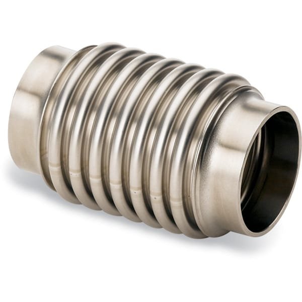
Hydraulically Formed Bellows with Standard Thick Wall Tube Ends
At TFM, we manufacture tube end (tubulated) formed bellows using high-quality 300 series stainless steel hoses. These hydraulically formed bellows are designed to offer both durability and flexibility across various applications.
MH-Series Bellows
- Material: Constructed from thin 300 series stainless steel, these bellows are made to withstand numerous flexing cycles, ensuring long-term reliability.
Key Features of Our Flexible Hoses:
- Unbraided Flexible Hoses: These can extend up to 10% beyond their functional length and compress by as much as 15%, making them versatile for dynamic environments.
- Braided Flexible Hoses: Equipped with a braided sheath, these hoses are designed to protect the convoluted hose from external damage, enhancing longevity and performance.
- Short Flexible Hoses: Ideal for adjusting minor misalignments in components, ensuring seamless connectivity in tight spaces.
- Longer Flexible Hoses: Commonly used as roughing lines, these are perfect for applications requiring greater flexibility and distance coverage.
TFM offers these stainless steel hoses to meet a wide range of industrial needs, providing solutions for both small adjustments and larger piping systems.
Ordering Table
| Drawing | Length | WallThickness | TubeOD | Part Number |

| 3 | 0.008 | 0.75 | MH-TE-A03 |
|
| 6 | 0.008 | 0.75 | MH-TE-A06 |
|
| 10 | 0.008 | 0.75 | MH-TE-A10 |
|
| 12 | 0.008 | 0.75 | MH-TE-A12 |
|
| 18 | 0.008 | 0.75 | MH-TE-A18 |
|
| 20 | 0.008 | 0.75 | MH-TE-A20 |
|
| 24 | 0.008 | 0.75 | MH-TE-A24 |
|
| 30 | 0.008 | 0.75 | MH-TE-A30 |
|
| 36 | 0.008 | 0.75 | MH-TE-A36 |
|
| 40 | 0.008 | 0.75 | MH-TE-A40 |
|
| 48 | 0.008 | 0.75 | MH-TE-A48 |
|
| 3 | 0.008 | 1 | MH-TE-B03 |
|
| 6 | 0.008 | 1 | MH-TE-B06 |
|
| 10 | 0.008 | 1 | MH-TE-B10 |
|
| 12 | 0.008 | 1 | MH-TE-B12 |
|
| 18 | 0.008 | 1 | MH-TE-B18 |
|
| 20 | 0.008 | 1 | MH-TE-B20 |
|
| 24 | 0.008 | 1 | MH-TE-B24 |
|
| 30 | 0.008 | 1 | MH-TE-B30 |
|
| 36 | 0.008 | 1 | MH-TE-B36 |
|
| 40 | 0.008 | 1 | MH-TE-B40 |
|
| 48 | 0.008 | 1 | MH-TE-B48 |
|
| 3 | 0.010 | 1.5 | MH-TE-C03 |
|
| 6 | 0.010 | 1.5 | MH-TE-C06 |
|
| 10 | 0.010 | 1.5 | MH-TE-C10 |
|
| 18 | 0.010 | 1.5 | MH-TE-C18 |
|
| 20 | 0.010 | 1.5 | MH-TE-C20 |
|
| 24 | 0.010 | 1.5 | MH-TE-C24 |
|
| 30 | 0.010 | 1.5 | MH-TE-C30 |
|
| 36 | 0.010 | 1.5 | MH-TE-C36 |
|
| 40 | 0.010 | 1.5 | MH-TE-C40 |
|
| 48 | 0.010 | 1.5 | MH-TE-C48 |
|
| 4 | 0.012 | 2 | MH-TE-D04 |
|
| 6 | 0.012 | 2 | MH-TE-D06 |
|
| 10 | 0.012 | 2 | MH-TE-D10 |
|
| 12 | 0.012 | 2 | MH-TE-D12 |
|
| 18 | 0.012 | 2 | MH-TE-D18 |
|
| 20 | 0.012 | 2 | MH-TE-D20 |
|
| 24 | 0.012 | 2 | MH-TE-D24 |
|
| 30 | 0.012 | 2 | MH-TE-D30 |
|
| 36 | 0.012 | 2 | MH-TE-D36 |
|
| 40 | 0.012 | 2 | MH-TE-D40 |
|
| 48 | 0.012 | 2 | MH-TE-D48 |
|
| 6 | 0.012 | 2.5 | MH-TE-E06 |
|
| 6 | 0.016 | 3 | MH-TE-F06 |
|
| 6 | 0.015 | 4 | MH-TE-G06 |
|
| 6 | 0.015 | 5 | MH-TE-H06 |
|
| 8 | 0.015 | 6 | MH-TE-J08 |
|
| 3 | 0.008 | 0.25 | MH-TE-X03 |
|
| 6 | 0.008 | 0.25 | MH-TE-X06 |
|
| 10 | 0.008 | 0.25 | MH-TE-X10 |
|
| 12 | 0.008 | 0.25 | MH-TE-X12 |
|
| 18 | 0.008 | 0.25 | MH-TE-X18 |
|
| 20 | 0.008 | 0.25 | MH-TE-X20 |
|
| 24 | 0.008 | 0.25 | MH-TE-X24 |
|
| 30 | 0.008 | 0.25 | MH-TE-X30 |
|
| 36 | 0.008 | 0.25 | MH-TE-X36 |
|
| 40 | 0.008 | 0.25 | MH-TE-X40 |
|
| 48 | 0.008 | 0.25 | MH-TE-X48 |
|
| 3 | 0.008 | 0.38 | MH-TE-Y03 |
|
| 6 | 0.008 | 0.38 | MH-TE-Y06 |
|
| 10 | 0.008 | 0.38 | MH-TE-Y10 |
|
| 12 | 0.008 | 0.38 | MH-TE-Y12 |
|
| 18 | 0.008 | 0.38 | MH-TE-Y18 |
|
| 20 | 0.008 | 0.38 | MH-TE-Y20 |
|
| 24 | 0.008 | 0.38 | MH-TE-Y24 |
|
| 30 | 0.008 | 0.38 | MH-TE-Y30 |
|
| 36 | 0.008 | 0.38 | MH-TE-Y36 |
|
| 40 | 0.008 | 0.38 | MH-TE-Y40 |
|
| 48 | 0.008 | 0.38 | MH-TE-Y48 |
|
| 3 | 0.008 | 0.5 | MH-TE-Z03 |
|
| 6 | 0.008 | 0.5 | MH-TE-Z06 |
|
| 10 | 0.008 | 0.5 | MH-TE-Z10 |
|
| 12 | 0.008 | 0.5 | MH-TE-Z12 |
|
| 18 | 0.008 | 0.5 | MH-TE-Z18 |
|
| 20 | 0.008 | 0.5 | MH-TE-Z20 |
|
| 24 | 0.008 | 0.5 | MH-TE-Z24 |
|
| 30 | 0.008 | 0.5 | MH-TE-Z30 |
|
| 36 | 0.008 | 0.5 | MH-TE-Z36 |
|
| 40 | 0.008 | 0.5 | MH-TE-Z40 |
|
| 48 | 0.008 | 0.5 | MH-TE-Z48 |

Reviews
There are no reviews yet.