KF (QF) HV Blank Stubs (304L SS): Rugged Port Sealing for Demanding High-Vacuum Applications
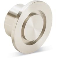
KF (QF) HV Blank Stubs (304L SS) are heavy-duty sealing components designed to isolate and cap unused ports in high-vacuum (HV) systems. Built with durability and system integrity in mind, these blank stubs are fully compliant with ISO-standard KF (Klein Flansche) fittings and are ideal for foreline and through-line vacuum plumbing as well as chamber port sealing in harsh or chemically active environments.
Each KF (QF) HV Blank Stub (304L SS) features a standard KF flange on one end and a sealed tube end on the other. The flange is machined to precise tolerances, ensuring reliable mating with other KF components using standard elastomeric o-rings and centering rings. When secured with a circumferential clamp—whether via wing-nut, thumbscrew, or lever lock—the connection supports vacuum levels as low as 10⁻⁸ Torr, making it suitable for most laboratory and industrial HV operations.
Manufactured from 304L stainless steel, these blank stubs provide superior corrosion resistance, thermal stability, and weld compatibility. 304L is specifically recommended for vacuum systems exposed to corrosive gases, high temperatures, or reactive chemicals, where aluminum or brass fittings may fail or degrade over time. Its low carbon content minimizes the risk of intergranular corrosion after welding or long-term thermal cycling, ensuring long-lasting reliability even in the most demanding UHV environments.
The use of elastomeric o-rings in KF connections is critical, as they determine the sealing temperature range—typically from 0 °C to 120–180 °C—and the ultimate vacuum achievable. These o-rings sit in a centering ring that both aligns and compresses during flange mating, maintaining vacuum integrity even under repeated installation cycles.
KF (QF) HV Blank Stubs (304L SS) are commonly used in semiconductor tools, research vacuum chambers, deposition systems, and analytical instruments where sealing unused ports is necessary for cleanliness, safety, or modularity. Their rugged all-metal construction also makes them suitable for systems that undergo frequent venting, bakeouts, or mechanical repositioning.
TFM offers these blank stubs in all standard KF sizes, including KF16, KF25, KF40, and KF50, with each unit manufactured to vacuum-grade specifications. Custom options such as vent holes, extended lengths, or electropolished finishes are available to meet specialized application needs.
In summary, KF (QF) HV Blank Stubs (304L SS) provide a high-strength, vacuum-compatible solution for capping unused KF ports in systems requiring maximum material performance. Their resistance to corrosion, mechanical wear, and thermal stress makes them a preferred choice in advanced vacuum system designs across research, aerospace, and semiconductor sectors.
Ordering Table
| Flange Size/OD | Type | Flange Material | Drawing | Overall Length | VacuCADSM | Part Number |
| KF10 (1.18" OD) | Stub, Blank | 304L SS |

| 0.75 | (please log in) | QF10-050-US |
| KF16 (1.18" OD) | Stub, Blank | 304L SS |

| 0.75 | (please log in) | QF16-075-US |
| KF25 (1.57" OD) | Stub, Blank | 304L SS |

| 0.75 | (please log in) | QF25-100-US |
| KF40 (2.16" OD) | Stub, Blank | 304L SS |

| 1.00 | (please log in) | QF40-150-US |
| KF50 (2.95" OD) | Stub, Blank | 304L SS |

| 1.00 | (please log in) | QF50-200-US |
Accessories Table
| Description | For | Per Package | Part Number |
| Cast Clamps (SS) | KF10, KF16 Flanges | 1 | QF16-075-CS |
| Cast Clamps (SS) | KF25 Flanges | 1 | QF25-100-CS |
| Cast Clamps (SS) | KF40 Flanges | 1 | QF40-150-CS |
| Cast Clamps (SS) | KF50 Flanges | 1 | QF50-200-CS |
| Cast Clamps (Aluminum) | KF10, KF16 Flanges | 1 | QF16-075-C |
| Cast Clamps (Aluminum) | KF25 Flanges | 1 | QF25-100-C |
| Cast Clamps (Aluminum) | KF40 Flanges | 1 | QF40-150-C |
| Cast Clamps (Aluminum) | KF50 Flanges | 1 | QF50-200-C |
| Lever Clamps (Aluminum) | KF10, KF16 Flanges | 1 | QF16-075-CHA |
| Lever Clamps (Aluminum) | KF25 Flanges | 1 | QF25-100-CHA |
| Lever Clamps (Aluminum) | KF40 Flanges | 1 | QF40-150-CHA |
| Centering Ring (SS with Fluorocarbon O-Ring) | KF10 Flanges | 1 | QF10-050-SRV |
| Centering Ring (SS with Fluorocarbon O-Ring) | KF16 Flanges | 1 | QF16-075-SRV |
| Centering Ring (SS with Fluorocarbon O-Ring) | KF25 Flanges | 1 | QF25-100-SRV |
| Centering Ring (SS with Fluorocarbon O-Ring) | KF40 Flanges | 1 | QF40-150-SRV |
| Centering Ring (SS with Fluorocarbon O-Ring) | KF50 Flanges | 1 | QF50-200-SRV |
Reviews
There are no reviews yet.