KF (QF) HV Bored Stainless Steel Flanges (Metric Tube): Precision KF Vacuum Interfaces for Metric Tubing
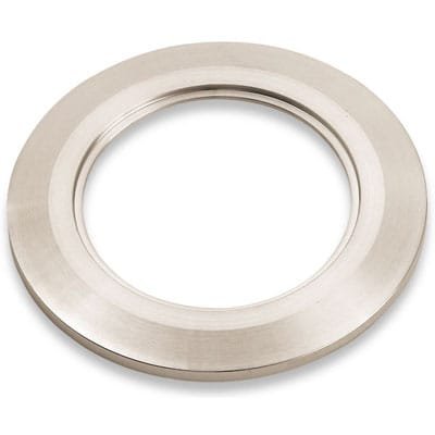
KF (QF) HV Bored Stainless Steel Flanges (Metric Tube) are engineered for high-vacuum (HV) systems requiring accurate and durable flange interfaces matched to metric tubing dimensions. These specialized flanges feature a precision-machined bore through the center, enabling seamless alignment and welding or joining with metric-size tubes while preserving full KF quick-flange compatibility.
Each KF (QF) HV Bored Stainless Steel Flange (Metric Tube) is crafted from corrosion-resistant 304L stainless steel, a material selected for its excellent performance in chemically aggressive and high-temperature environments. The flange design incorporates the standard sexless KF (QF) geometry, allowing easy mating with other KF components regardless of orientation, and enabling tool-free assembly using common quick-clamp systems.
The bored opening at the center of each KF (QF) HV Bored Stainless Steel Flange (Metric Tube) is dimensioned precisely to fit standard metric tube sizes, such as 12 mm, 16 mm, 25 mm, or 40 mm. This provides engineers with a clean, concentric surface for welding, brazing, or mechanical tube joining. It is particularly useful in custom vacuum lines, HV instrumentation ports, and manifold assemblies where non-standard tubing must be adapted to standard KF hardware.
The sealing system used with KF (QF) HV Bored Stainless Steel Flanges (Metric Tube) consists of a rubber or elastomeric o-ring seated inside a centering ring. When compressed between two chamfered flange faces using a circumferential clamp—tightened with a wing-nut, thumbscrew, bolt, or over-center lever—the o-ring ensures a leak-tight seal down to 10⁻⁸ torr. The chamfered back surface of the flange plays a critical role in ensuring proper alignment and even pressure distribution during sealing.
Thanks to the 304L stainless steel construction, KF (QF) HV Bored Stainless Steel Flanges (Metric Tube) perform reliably across a wide thermal range, typically between 0 °C and 120–180 °C, depending on the o-ring material selected. This makes them highly suited for both laboratory-scale vacuum setups and industrial HV systems operating in more demanding environments.
TFM offers KF (QF) HV Bored Stainless Steel Flanges (Metric Tube) in standard KF sizes—including KF16, KF25, KF40, and KF50—with bore diameters tailored to match the most common metric tubing dimensions. For specialized configurations, such as tight tolerances, extended lengths, or electropolished finishes for ultra-clean applications, custom fabrication is also available upon request.
In summary, KF (QF) HV Bored Stainless Steel Flanges (Metric Tube) offer a clean, secure, and dimensionally accurate transition point between metric tube assemblies and KF high-vacuum systems. Their robust stainless steel construction, precise machining, and vacuum-sealing reliability make them a go-to choice for vacuum professionals working with international or metric-based infrastructure.
Ordering Table
| Flange Size/OD | Type | Flange Material | Drawing | Part Number |
| KF10 (1.18" OD) | Bored | 316L SS |

| QF10-055-SBB |
| KF16 (1.18" OD) | Bored | 316L SS |
| QF16-079-SBB |
| KF25 (1.57" OD) | Bored | 316L SS |
| QF25-110-SBB |
| KF40 (2.16" OD) | Bored | 316L SS |
| QF40-175-SBB |
| KF50 (2.95" OD) | Bored | 316L SS |
| QF50-224-SBB |
Accessories Table
| Description | For | Per Package | Part Number |
| Cast Clamps (SS) | KF10, KF16 Flanges | 1 | QF16-075-CS |
| Cast Clamps (SS) | KF25 Flanges | 1 | QF25-100-CS |
| Cast Clamps (SS) | KF40 Flanges | 1 | QF40-150-CS |
| Cast Clamps (SS) | KF50 Flanges | 1 | QF50-200-CS |
| Cast Clamps (Aluminum) | KF10, KF16 Flanges | 1 | QF16-075-C |
| Cast Clamps (Aluminum) | KF25 Flanges | 1 | QF25-100-C |
| Cast Clamps (Aluminum) | KF40 Flanges | 1 | QF40-150-C |
| Cast Clamps (Aluminum) | KF50 Flanges | 1 | QF50-200-C |
| Lever Clamps (Aluminum) | KF10, KF16 Flanges | 1 | QF16-075-CHA |
| Lever Clamps (Aluminum) | KF25 Flanges | 1 | QF25-100-CHA |
| Lever Clamps (Aluminum) | KF40 Flanges | 1 | QF40-150-CHA |
| Centering Ring (SS with Fluorocarbon O-Ring) | KF25 Flanges | 1 | QF25-100-SRV |
| Centering Ring (SS with Fluorocarbon O-Ring) | KF40 Flanges | 1 | QF40-150-SRV |
| Centering Ring (SS with Fluorocarbon O-Ring) | KF50 Flanges | 1 | QF50-200-SRV |
| Centering Ring (SS with Fluorocarbon O-Ring) | KF10 Flanges | 1 | QF10-050-SRV |
| Centering Ring (SS with Fluorocarbon O-Ring) | KF16 Flanges | 1 | QF16-075-SRV |
| Description | For | Per Package | Part Number |


Reviews
There are no reviews yet.