Generic selectors
Exact matches only
Search in title
Search in content
Post Type Selectors

Weldable Tube Reducer Crosses

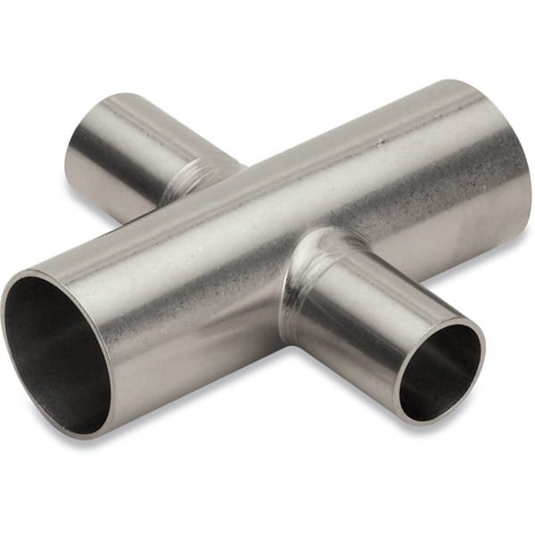
Weldable Tube Reducer Crosses for High-Vacuum and Semiconductor Systems

Weldable Tube Reducer Crosses from TFM are engineered to meet the stringent demands of ultra-high vacuum (UHV) environments and semiconductor process systems. Fabricated from 304 series stainless steel, these reducer crosses are ideal for roughing lines, foreline assemblies, and pump exhaust routes in cleanroom and subfab installations.

These fittings are a specialized variant of our weldable cross tube fittings, with a key differentiator—their reducer design, which allows connection between two different tube sizes within a single cross fitting. This feature offers exceptional system design flexibility, especially when interfacing components across varying process scales.

Each weldable reducer cross is manufactured using the pulled-port technique and completed with full-penetration butt welds. This method ensures crevice-free joints, a critical requirement for contamination-sensitive processes where particle generation must be minimized. The internal surfaces are cleaned and processed to achieve vacuum performance levels as low as 10⁻¹³ Torr, making them suitable for even the most demanding UHV systems.

The fittings are capable of withstanding extreme thermal cycling, with a working temperature range from 200°C to 450°C. This makes them not only suitable for ambient semiconductor processes but also for cryogenic or high-temperature environments commonly found in plasma processing, PVD, or CVD systems.

Key Features of Weldable Tube Reducer Crosses:

  • Material: Fabricated from high-purity 304 stainless steel.

  • Reducer Geometry: Designed to connect tubes of different diameters, ensuring seamless transitions in complex vacuum piping layouts.

  • UHV-Ready: Cleaned to support vacuum levels down to >10⁻¹³ Torr.

  • Butt Weld Integrity: Features full-penetration welds using the pulled-port method for superior joint strength.

  • Crevice-Free Design: Prevents contamination and particle traps.

  • Thermal Compatibility: Operates reliably from 200°C to 450°C.

  • Custom Options: Available with non-standard tube sizes or wall thicknesses; flanged reducer crosses can also be provided upon request.

Common Applications:

  • Semiconductor vacuum plumbing systems

  • High-vacuum pump exhaust lines

  • UHV scientific instrumentation and research setups

  • Integrated systems for process gas distribution

  • Thermal processing equipment requiring variable tube size connections

Whether you’re building a new vacuum manifold or upgrading existing semiconductor tooling, TFM’s Weldable Tube Reducer Crosses offer the clean, durable, and configurable solution your system requires.

Ordering Table

Drawing DimA DimB TubeOD TubeOD 2 Part Number
Tooltip 1.88 1 1 0.50 G-9WR-100050
Tooltip 1.88 1.12 1 0.75 G-9WR-100075
Tooltip 2.25 1.25 1.5 0.50 G-9WR-150050
Tooltip 2.25 1.38 1.5 0.75 G-9WR-150075
Tooltip 2.25 2.13 1.5 1 G-9WR-150100
Tooltip 3 1.5 2 0.50 G-9WR-200050
Tooltip 3 1.63 2 0.75 G-9WR-200075
Tooltip 3 2.5 2 1.5 G-9WR-200150
Tooltip 3 2.75 2.5 1.5 G-9WR-250150
Tooltip 3 3.25 2.5 2 G-9WR-250200
Tooltip 3.25 3 3 1.5 G-9WR-300150
Tooltip 3.25 3.5 3 2 G-9WR-300200
Tooltip 3.25 3.25 3 2.5 G-9WR-300250
Tooltip 3.88 3.5 4 1.5 G-9WR-400150
Tooltip 3.88 4 4 2 G-9WR-400200
Tooltip 3.88 3.75 4 2.5 G-9WR-400250
Tooltip 3.88 3.75 4 3 G-9WR-400300
Tooltip 4.25 4.38 5 4 G-9WR-500400
Tooltip 5 4.5 6 1.5 G-9WR-600150
Tooltip 5 5 6 2 G-9WR-600200
Tooltip 5 4.75 6 2.5 G-9WR-600250
Tooltip 5 4.75 6 3 G-9WR-600300
Tooltip 5 4.88 6 4 G-9WR-600400
Tooltip 5 4.75 6 5 G-9WR-600500
Tooltip 7 6 8 6 G-9WR-800600

Reviews

There are no reviews yet.

Be the first to review “Weldable Tube Reducer Crosses”

Your email address will not be published. Required fields are marked *

FAQ

Tube fittings are designed for tubes (measured by outside diameter and wall thickness) used in high-pressure and instrumentation applications, whereas pipe fittings are for pipes (identified by nominal pipe size) primarily used in fluid transport.


Common valve types include ball valves, gate valves, check valves, butterfly valves, and globe valves. Each serves a specific function—from quick shutoff (ball/gate valves) to flow regulation (globe valves).

 
  • For tubing, measure the outside diameter; for pipes, refer to the nominal pipe size (using conversion charts if needed). Always match the valve or fitting size to your pipe’s dimensions and flow requirements.

  • Frequently used thread types include NPT (National Pipe Tapered), BSP (British Standard Pipe), and UNC, along with slip-fit options that rely on compression or fusion rather than threads.

Interchangeability depends on manufacturer specifications and certification. Always verify compatibility via manufacturer guides or certified interchangeability charts.

 
  • A coupling is a short, straight fitting used to join two pipes or tubes. It provides a secure, leak-tight connection and can sometimes serve to extend or repair piping runs.

Consider valve type, pressure and temperature ratings, material compatibility with your fluid, actuation method (manual or automatic), and maintenance requirements.

 
  • Valves regulate flow by opening, closing, or partially obstructing the pathway. Their mechanisms (such as the rotation of a ball or the linear movement of a gate) determine the speed and precision of flow control.

  • A flange is a flat, circular component used to connect pipes, valves, or other equipment. Bolted together with gaskets, flanges provide a secure, leak-proof joint that facilitates both assembly and maintenance.

  • Manual valves require physical operation via handles or levers, whereas actuated valves use mechanisms—pneumatic, electric, or hydraulic—to open and close automatically or remotely.

  • Issues include leaks caused by improper installation, over-tightening, degraded seals, material incompatibility, and fatigue from repeated cycling. Regular inspection and proper installation practices help mitigate these problems.

Regular maintenance involves periodic inspections, cleaning or replacing worn seals, ensuring proper torque during installation, and adhering to manufacturer guidelines and local plumbing codes to preserve system integrity.


Shopping Cart
Scroll to Top