Quick answer: A vacuum viewport shutter is a movable shield installed on the chamber side of an optical viewport. It is normally closed when deposition, etching, plasma exposure, or particle generation could coat or damage the window, then moved clear when visual or optical access is required. The shutter does not isolate vacuum like a valve and does not by itself guarantee a clean optical path. Correct selection depends on the flange and viewport geometry, clear aperture, blade coverage, actuation and feedthrough, vacuum and bakeout requirements, process exposure, position indication, interlocks, and maintenance access.
What Is a Viewport Shutter?
A viewport provides a sealed optical path through a vacuum-chamber wall. Depending on the application, that path may support observation, illumination, spectroscopy, pyrometry, laser entry, imaging, or alignment. The transparent element and its seal remain part of the vacuum boundary.
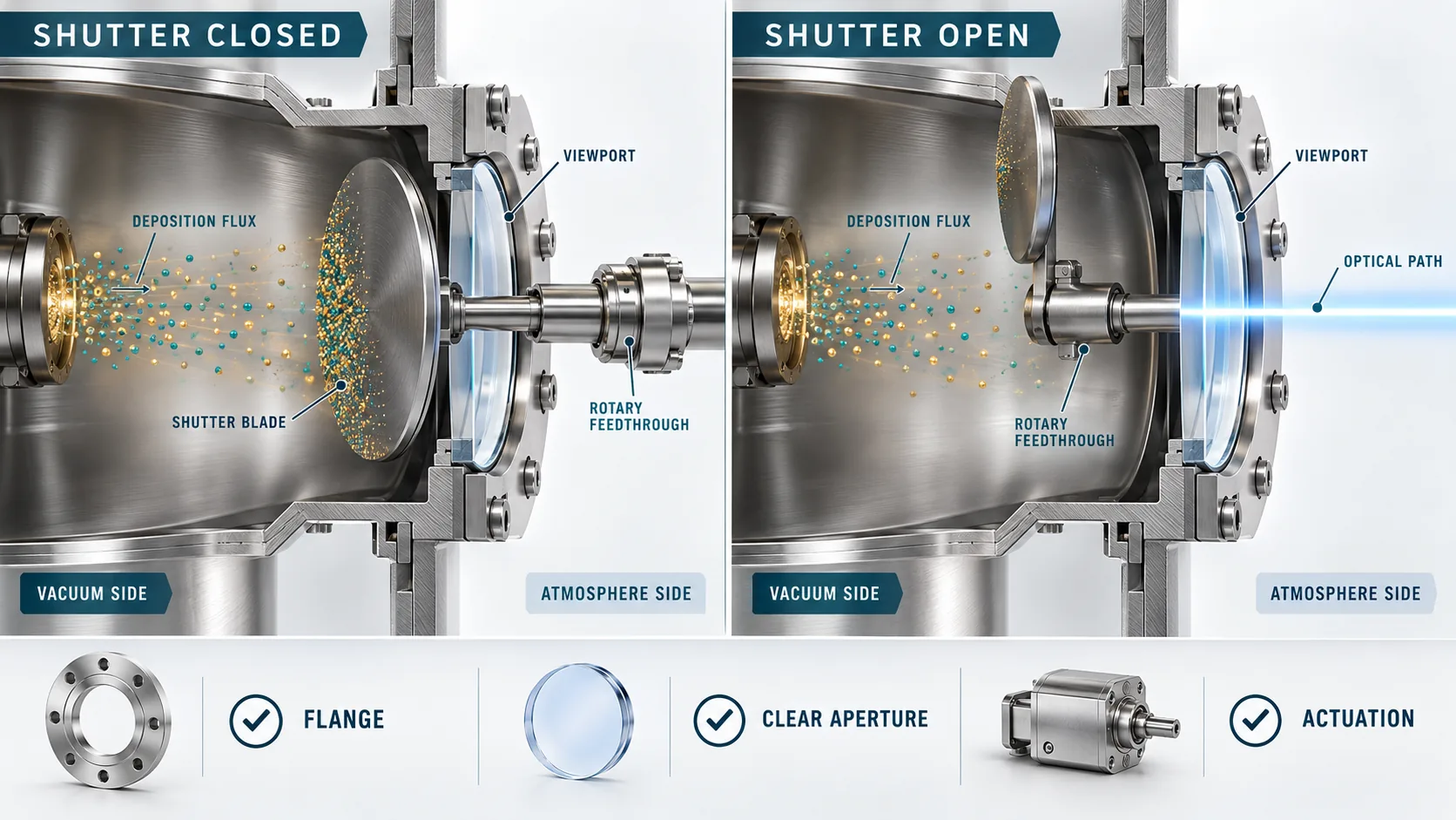
A viewport shutter is a separate protective mechanism. Its blade swings, rotates, slides, or translates between a covered position and a clear position. When closed, the blade intercepts at least part of the direct line of sight between the process and the window. When open, the blade must clear the required optical cone rather than merely expose the center of the glass.
This article owns the working-principle and engineering-selection intent. For purchasable configurations and current ordering details, use the Manual Viewport Shutters and Pneumatic Viewport Shutters product pages.
How a Viewport Shutter Works
Closed position: intercept process exposure
The blade is placed between the viewport and the deposition source, plasma, beam, or contamination source. It may reduce direct coating of the window and can also receive radiative heat or particles that otherwise have line of sight to the optical surface. Protection is geometry-dependent: a blade that covers the nominal glass diameter may still leave an oblique path around its edge.
Open position: clear the optical path
The drive moves the blade outside the required field of view or beam envelope. Required clearance should be defined from the actual optical cone, incidence angle, viewport recess, working distance, and alignment tolerance. “Open” is a mechanical state; it is not proof that transmission, focus, or beam clipping meets the instrument requirement.
Actuation transfers motion through the vacuum boundary
Manual and pneumatic products commonly use a rotary drive or feedthrough. Other assemblies may use motorized or linear mechanisms. The feedthrough, shaft, bearings, stops, lubricants if any, and actuator must all be suitable for the specified environment. A shutter blade is not a vacuum seal, and its actuation mechanism should not be confused with a gate valve.
Manual vs Pneumatic Viewport Shutters
| Selection question | Manual actuation | Pneumatic actuation |
|---|---|---|
| How often must it move? | Suited to operator-controlled or infrequent changes when access and procedure allow | Useful for repeated or recipe-controlled movement after cycle requirements are confirmed |
| Remote operation | Requires an operator at the control point | Can be integrated with valves, regulators, controls, and permitted interlocks |
| Utilities | No pneumatic supply; still requires a compatible feedthrough and handle arrangement | Requires compatible gas supply, pressure control, tubing, valve logic, and safe exhaust arrangement |
| State feedback | May rely on visual or procedural confirmation unless indicators are specified | Position sensing may be specified; command state alone is not position proof |
| Failure response | Defined by handle position and operating procedure | Define behavior for loss of air, power, signal, or actuator force for the actual design |
Seven Engineering Checks Before Selection
1. Flange and mounting interface
Specify the flange standard and nominal size, mating orientation, available bolt and wrench access, viewport recess, chamber-wall thickness, and nearby obstructions. A matching nominal flange does not guarantee that the blade, drive, or handle clears surrounding hardware.
2. Clear aperture and optical cone
Distinguish flange size, viewport viewing diameter, shutter-blade diameter, and required clear aperture. Provide a drawing when the path is off-axis, converging, scanning, or uses a wide field of view.
3. Coverage and line of sight
Define the process source location and the directions from which coating, plasma, heat, or particles can reach the viewport. A shutter can reduce direct exposure while secondary scattering, re-emission, or edge paths still contaminate the window.
4. Vacuum and bakeout compatibility
Specify the required operating pressure range, leak-rate criterion, cleaning state, materials restrictions, and whether the installed shutter will remain during bakeout. Maximum temperature depends on the complete assembly, including seals, bearings, sensors, wiring, lubricants, actuator separation, and mounting. Do not assign one UHV or bakeout rating to every viewport shutter.
5. Actuation, torque, and cycle profile
Record actuation type, available utilities, motion angle or travel, desired speed, cycle frequency, accumulated exposure, and any required adjustable stops. Deposited material can change mass, balance, friction, clearance, and required torque over time.
6. Position indication and interlocks
If exposing the viewport at the wrong time could damage an optic or affect a process, define whether open and closed positions must be independently sensed. An interlock should use verified state and the equipment safety architecture—not assume that a control command completed the motion.
7. Cleaning and service access
Specify how the blade and actuator are removed, whether the viewport can stay installed, how deposits are handled, and what inspection determines return to service. Cleaning chemistry and mechanical methods must be compatible with the blade, window, seals, and deposited material.
Common Failure Modes and What to Check
| Symptom | Possible contributors | Evidence to collect |
|---|---|---|
| Viewport still coats when closed | Incomplete coverage, oblique line of sight, scattering, blade not reaching stop | Source/port drawing, deposit pattern, blade position, stop setting |
| Optical path clips when open | Clear-aperture mismatch, blade travel, shaft or recess intrusion, alignment shift | Beam envelope, field of view, aperture map, open-position measurement |
| Slow, rough, or incomplete motion | Deposit buildup, interference, drive wear, utility change, thermal distortion | Cycle count, pressure/utility record, torque or timing trend, visual inspection |
| Position signal disagrees with blade | Sensor alignment, loose coupling, logic mapping, stop shift | Physical state, independent sensor test, wiring and logic review |
| Vacuum performance changes after service | Contamination, damaged seal/feedthrough, incorrect assembly, trapped volume | Leak test, pumpdown trend, service record, cleaned-part inspection |
RFQ Checklist for a Viewport Shutter
- Flange standard, nominal size, material, and mounting orientation
- Viewport type, viewing diameter, recess, and required clear aperture
- Process source location, line of sight, and material or plasma exposure
- Manual or pneumatic actuation, utilities, control interface, and cycle profile
- Required motion, open clearance, blade coverage, and adjustable-stop needs
- Operating pressure range, leak criterion, cleaning level, and materials restrictions
- Bakeout temperature and whether the complete shutter remains installed
- Open/closed indication, interlock requirements, and defined loss-of-utility state
- Space envelope, collision risks, service access, and drawing requirements
- Documentation, inspection, packaging, and acceptance-test requirements
Use the relevant product page to identify a starting configuration, then contact TFM with the complete interface and process information. Current public product tables are ordering aids, not substitutes for an approved chamber drawing.
Evidence Boundary
Evidence boundary: This guide describes common viewport-shutter functions and selection questions. It does not assign a universal vacuum rating, bakeout temperature, input pressure, cycle life, leak rate, actuation torque, material set, optical transmission, or fail-safe behavior. Confirm those values from the exact part record, drawing, materials list, actuator/control design, and acceptance requirements.