
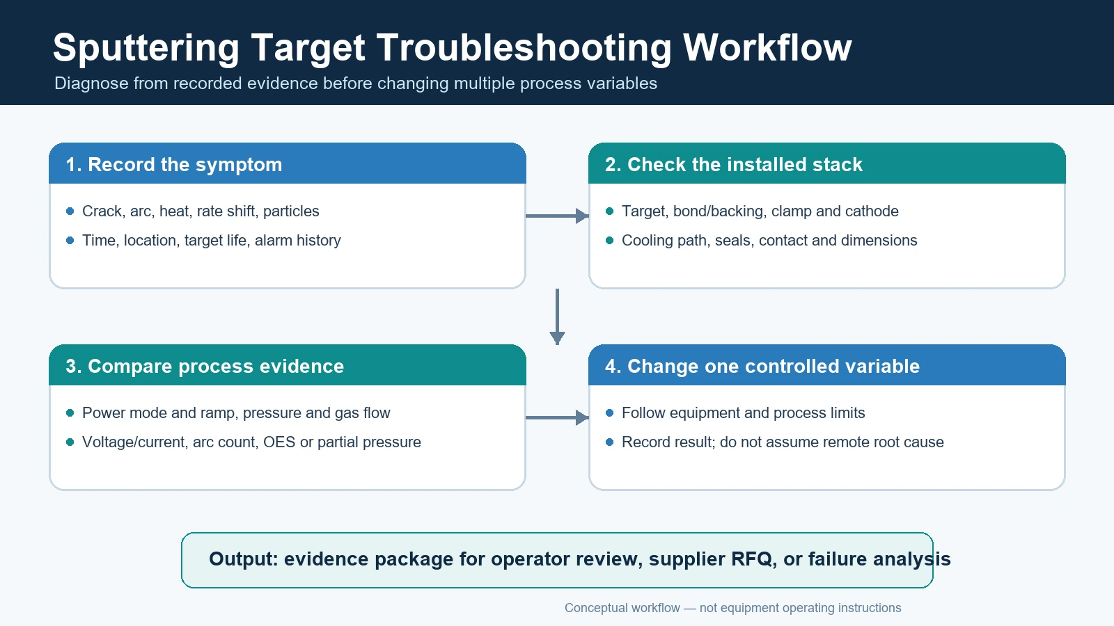
Sputtering target troubleshooting should start with the observed symptom and the installed system—not with a universal power limit or an assumed target defect. Cracking, arcing, overheating, rate drift, particles, bond indications, and film-composition changes can each have several interacting causes. Record the target, cathode, cooling, power, gas, pressure, time, maintenance, and inspection evidence before changing multiple variables.
This guide organizes evidence for operator review, supplier discussion, and failure analysis. It does not replace the sputtering-system manual, approved process window, electrical safety procedure, or site-specific operating controls.
Sputtering target problems: symptom-first diagnostic matrix
| Observed symptom | Possible contributors to investigate | Evidence to collect first |
|---|---|---|
| Target crack or fracture | Handling damage, unsupported span, clamp load, residual stress, thermal gradient, local hot region, arc event, bond defect, or incompatible installation geometry | Crack origin and direction, photographs, target and assembly drawing, installation record, power history, cooling record, and bond inspection if applicable |
| Frequent arcing | Insulating deposits, reactive-process state, particles or flakes, shield condition, target-edge or racetrack deposits, power-supply response, pressure, or contamination | Arc count and timing, voltage/current trace, power mode, gas and pressure history, target/shield photographs, chamber-cleaning record, and film/deposit identity |
| Target or backing overheating | Cooling restriction, incorrect flow path, poor target-to-cathode contact, local bond void, incorrect assembly thickness, high local power loading, eroded geometry, or temperature excursion | Coolant inlet/outlet data, flow and pressure, installed stack drawing, contact surfaces, power and duty cycle, temperature evidence, and ultrasonic map if specified |
| Deposition-rate shift | Reactive target-surface coverage, target erosion, pressure or gas-distribution change, source-to-substrate geometry, power delivery, shutter/shield buildup, or measurement drift | Rate history at the same recipe, voltage/current, reactive-gas response, target life, erosion profile, pressure calibration, and thickness-monitor verification |
| Particles or flakes | Chamber/shield deposit release, redeposition at target edges, arcing, handling contamination, target-surface defects, bond-edge exposure, or process deposits | Particle composition and location, chamber map, target/shield photographs, cleaning history, arc history, and microscopy where available |
| Film composition or uniformity drift | Reactive-process state, target composition or segregation, multi-source balance, erosion profile, gas distribution, substrate motion, geometry, or analytical variation | Film analysis method and map, target identity and CoA, recipe history, source powers, target life, gas/pressure data, and witness samples |
Establish a comparable baseline before changing the process
A useful comparison holds the measurement method and relevant operating state constant. “The target ran hotter” is not enough unless the target life, installed thickness, cooling state, power mode, pressure, duty cycle, and measurement location are known. A new target, a deeply eroded target, and a replacement assembly with a different total height may not have the same thermal or electrical behavior.
- Record target material, composition, purity basis, dimensions, shape, backing or carrier, bond method, drawing revision, and installed orientation.
- Record cathode or gun manufacturer/model, clamp or keeper arrangement, cooling configuration, seals, and contact-surface condition.
- Save power mode, setpoint and delivered voltage/current, duty cycle, ramp history, arc counter, pressure, gas flows, and reactive-gas control signal.
- Identify when the symptom began: installation, conditioning, recipe transition, maintenance, target-life stage, or an isolated event.
- Change one controlled variable only within the equipment and process limits, then record the result.
Troubleshooting target cracking
A crack is evidence of stress, but the visible fracture alone does not identify the source. Mechanical loading can be introduced during handling, mounting, clamping, bonding, cooldown, or operation. Thermal gradients can add stress when heat generation and removal are not uniform. Brittle materials often require more conservative handling and support, but “ceramic” does not by itself prove that every target must use one bond or one ramp procedure.
Preserve the failed parts and photograph both faces, edges, crack origin, racetrack, bond or backing, and cathode contact. Compare flatness, thickness, clamp locations, unsupported areas, cooling evidence, power history, and any ultrasonic bond map. For assembly decisions, use the bonded vs unbonded sputtering target engineering guide. Do not assign the failure to “thermal shock” until other installation, interface, and handling evidence has been reviewed.
Troubleshooting overheating and cooling-path problems
The thermal path may include the target, direct contact or bond layer, backing plate or carrier, cathode body, coolant interface, and coolant circuit. A restriction or poor interface at any stage can change local temperature. Bonded assemblies add defined interfaces but can also introduce voids, incomplete wetting, temperature limits, thermal-expansion mismatch, or backing distortion. Unbonded assemblies depend strongly on contact, clamping, target geometry, and the cathode design.
Check the installed stack against the approved drawing. Review total height, target thickness, contact cleanliness, clamp or keeper condition, seal condition, coolant direction, flow/pressure data, inlet/outlet temperature, and maintenance history. Compare the symptom location with the erosion pattern and cooling geometry. A single generic power-density number cannot establish a safe limit across different materials, target sizes, cathodes, cooling systems, and bond designs.
Troubleshooting arcing and particle events
Arcing can involve insulating deposits, charge buildup, particles, target-edge or shield deposits, reactive-gas state, pressure, contamination, geometry, and the power supply’s arc-detection and recovery behavior. Research on reactive DC magnetron sputtering describes charge buildup on insulating compound layers as one arcing route; it does not mean that every arc has the same cause.
- Correlate arc count with time, power, gas transition, target-life stage, and maintenance events.
- Inspect target edges, racetrack, shields, anode areas, flakes, and loose particles without disturbing evidence needed for failure analysis.
- Review whether the configured power mode and arc handling are approved for the target/process combination.
- Use particle composition, location, and morphology where available; do not infer that porosity or target density alone caused the event.
Pulsed power and arc-handling electronics can be part of a qualified reactive-sputtering strategy, but they are not universal remote fixes. Apply only equipment-supported settings and validate film properties after a process change.
Troubleshooting target poisoning and reactive-process instability
In reactive sputtering, compound formation can occur at the target surface as well as at the substrate. The change in target-surface coverage can alter sputtering yield, voltage/current behavior, deposition rate, and reactive-gas consumption. Depending on the target/reactive-gas/system combination, the response may include a nonlinear transition or hysteresis between metallic, transition, and poisoned operating modes.
Do not diagnose poisoning from deposition rate alone. Compare reactive-gas flow and partial pressure where available, target voltage/current at the same power mode, optical-emission or other control signal, deposition rate, film composition, pumping state, and gas-distribution history. The dedicated target poisoning and hysteresis guide explains the mechanism and control options in detail.
Troubleshooting bond and backing-plate indications
Discoloration, a lifted area, solder movement, a changed ultrasonic indication, or backing distortion deserves review of the complete assembly and thermal history. Possible contributors include interface contamination, incomplete wetting, bond voids, temperature exposure, repeated power cycling, thermal-expansion mismatch, backing reuse, and local cooling conditions. These are investigation paths, not a remote determination that the bond process failed.
Specify the bond-area definition, nondestructive inspection method, report format, acceptance criteria, edge treatment, backing material and reuse condition in the RFQ. TFM provides separate paths for indium target bonding, elastomeric target bonding, and target bonding services; final suitability requires the target and cathode requirements.
Troubleshooting rate, composition, and uniformity drift
A film result is produced by the installed source and process, not by the target certificate alone. Rate or composition drift can involve target erosion, reactive-surface state, source power balance, pressure, gas distribution, substrate motion, source-to-substrate geometry, shield buildup, calibration, or analytical sampling. For co-sputtering, record each source’s delivered power and target-life state. For reactive sputtering, record the process signal used to control the transition region.
When investigating a target contribution, compare the CoA or material specification with the required composition basis, critical impurity limits, density or microstructure requirement, and the actual film-analysis method. “Higher purity” or “fully dense” cannot guarantee the film result, and one purity grade should not be assigned to every semiconductor or coating application.
Information to include in a troubleshooting RFQ
- Target material, formula/alloy/dopant composition, purity basis, and critical impurity limits
- Target dimensions, tolerances, surface finish, edge details, shape, and quantity
- Cathode or sputtering-gun manufacturer and model
- Target-only or complete assembly drawing, including backing/carrier and total installed height
- Bond method, backing material, bond-area and inspection requirements, if applicable
- Power mode, intended operating range, duty cycle, ramp method, and arc history
- Process gases, reactive gas, flow/control mode, pressure, and pumping configuration
- Cooling arrangement and available flow, pressure, and temperature records
- Target life or consumed thickness, erosion profile, and maintenance history
- Symptom timeline, location, photographs, instrument traces, particle/film analysis, and failed-part disposition
Browse the Sputtering Targets catalog, including pure metal targets, alloy sputtering targets, and ceramic sputtering targets. Send the available drawing and evidence through Contact TFM. Unknown fields should be labeled unknown rather than silently assumed.
Frequently asked questions
Does a sputtering target crack always mean poor target quality?
No. Material or manufacturing evidence may be relevant, but installation geometry, handling, clamping, bond/backing condition, cooling, thermal gradients, arc events, and process history can also contribute. Preserve the failed part and review the complete evidence set.
Can switching to a rotary target solve a sputtering problem?
Not by itself. Rotary and planar targets require compatible cathodes and have different erosion, cooling, maintenance, inventory, and cost considerations. Use the planar vs rotatable selection guide before changing geometry.
What should be changed first during sputtering troubleshooting?
First establish a recorded baseline and identify the symptom. Then select one controlled change that is permitted by the equipment manual and approved process limits. Changing power, gas, pressure, cooling, and hardware together prevents a defensible diagnosis.
Technical references
- S. Berg and T. Nyberg, Fundamental understanding and modeling of reactive sputtering processes, Thin Solid Films 476 (2005).
- J. Musil et al., Reactive magnetron sputtering of thin films: present status and trends, Thin Solid Films 475 (2005).
- Society of Vacuum Coaters, Arc Handling in Reactive DC Magnetron Sputter Deposition.
- Society of Vacuum Coaters, Heat Transfer and Stress Analysis of Bonded Sputter Target Assemblies.
- M.M. Waite and S.I. Shah, Target poisoning during reactive sputtering of silicon with oxygen and nitrogen, Materials Science and Engineering: B 140 (2007).