ASA HV 4-Way Crosses (grooved & flat flanges): Modular Vacuum Connectivity with Mixed ASA Sealing Interfaces
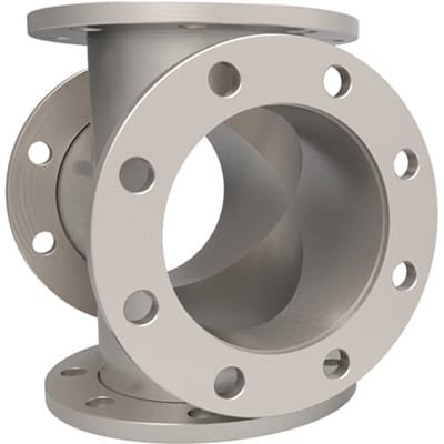
ASA HV 4-Way Crosses (grooved & flat flanges) from TFM are engineered for high-vacuum (HV) systems requiring durable, multi-port connectivity in a compact configuration. Fabricated from 304L stainless steel tubing, these crosses are designed to provide leak-tight, rotatable flange connections across four orthogonal axes. Each port is equipped with a rotatable ASA flange, available in a user-defined combination of grooved and flat styles.
This hybrid flange configuration aligns with the standard sexed ASA sealing system: grooved flanges accept elastomeric o-rings, while flat flanges provide the compression face. The flexibility of mixing grooved and flat flanges on a single cross makes these components highly adaptable for various vacuum chamber layouts and retrofit scenarios.
Key Features of ASA HV 4-Way Crosses (grooved & flat flanges):
High-Quality 304L Stainless Steel Construction
Delivers excellent mechanical strength and corrosion resistance, ensuring reliable performance in harsh HV environments and exposure to reactive gases or elevated temperatures.Mixed Grooved & Flat ASA Flanges
Flanges are rotatable and can be specified in any combination of grooved and flat, allowing compatibility with existing ASA flange hardware and o-ring seals.Four-Port Access Configuration
Provides efficient distribution points for pumps, gauges, feedthroughs, viewports, or process lines—ideal for compact high-vacuum setups or expansion nodes.Helium Leak Tested and Vacuum Cleaned
All ASA HV 4-Way Crosses (grooved & flat flanges) are cleaned to vacuum standards and tested to ensure leak-free operation down to 10⁻⁸ Torr.Custom Sizes and Reducer Options
Available in standard ASA flange diameters such as 4″, 6″, 8″, 10″, and 12″, with options for reducer crosses to interface different flange sizes, as well as non-standard tube lengths.
Typical Applications:
Vacuum chamber cross ports for instrumentation or gas routing
Foreline manifolds with mixed ASA interface requirements
Integration hubs for diagnostic, pumping, or process lines
Retrofit system upgrades using existing ASA-compatible components
Modular setups in R&D and industrial vacuum infrastructure
TFM also supplies ASA bolt sets, FKM and Buna-N o-rings, blank flanges, and custom machined adapters to fully support your system assembly.
In summary, ASA HV 4-Way Crosses (grooved & flat flanges) offer flexible, rotatable sealing interfaces for high-vacuum environments. Their mixed flange design, combined with stainless steel durability and customizable configuration, makes them ideal for engineers building or modifying complex vacuum systems.
Ordering Table
| Flange Size/OD | Drawing | Nominal Tube OD | Grooved Flanges | Dim A | Part Number |
| ASA 1 (4.25" OD) |

| 1-1/2 | Flange 1 | 2.5 | AF4C04X15G1R |
| ASA 1 (4.25" OD) |
| 1-1/2 | Flanges 1 & 2 | 2.5 | AF4C04X15G2R |
| ASA 1 (4.25" OD) |
| 1-1/2 | Flanges 1 & 3 | 2.5 | AF4C04X15G3R |
| ASA 1 (4.25" OD) |
| 1-1/2 | Flanges 1, 2 & 3 | 2.5 | AF4C04X15G4R |
| ASA 1.5 (5.00" OD) |
| 2 | Flange 1 | 3.25 | AF4C05X20G1R |
| ASA 1.5 (5.00" OD) |
| 2 | Flanges 1 & 2 | 3.25 | AF4C05X20G2R |
| ASA 1.5 (5.00" OD) |
| 2 | Flanges 1 & 3 | 3.25 | AF4C05X20G3R |
| ASA 1.5 (5.00" OD) |
| 2 | Flanges 1, 2 & 3 | 3.25 | AF4C05X20G4R |
| ASA 1.5 (5.00" OD) |
| 2-1/2 | Flange 1 | 3.25 | AF4C05X25G1R |
| ASA 1.5 (5.00" OD) |
| 2-1/2 | Flanges 1 & 2 | 3.25 | AF4C05X25G2R |
| ASA 1.5 (5.00" OD) |
| 2-1/2 | Flanges 1 & 3 | 3.25 | AF4C05X25G3R |
| ASA 1.5 (5.00" OD) |
| 2-1/2 | Flanges 1, 2 & 3 | 3.25 | AF4C05X25G4R |
| ASA 2 (6.00" OD) |
| 3 | Flange 1 | 3.5 | AF4C06X30G1R |
| ASA 2 (6.00" OD) |
| 3 | Flanges 1 & 2 | 3.5 | AF4C06X30G2R |
| ASA 2 (6.00" OD) |
| 3 | Flanges 1 & 3 | 3.5 | AF4C06X30G3R |
| ASA 2 (6.00" OD) |
| 3 | Flanges 1, 2 & 3 | 3.5 | AF4C06X30G4R |
| ASA 3 (7.50" OD) |
| 4 | Flange 1 | 5.12 | AF4C07X40G1R |
| ASA 3 (7.50" OD) |
| 4 | Flanges 1 & 2 | 5.12 | AF4C07X40G2R |
| ASA 3 (7.50" OD) |
| 4 | Flanges 1 & 3 | 5.12 | AF4C07X40G3R |
| ASA 3 (7.50" OD) |
| 4 | Flanges 1, 2 & 3 | 5.12 | AF4C07X40G4R |
| ASA 4 (9.00" OD) |
| 4 | Flange 1 | 5.12 | AF4C09X40G1R |
| ASA 4 (9.00" OD) |
| 4 | Flanges 1 & 2 | 5.12 | AF4C09X40G2R |
| ASA 4 (9.00" OD) |
| 4 | Flanges 1 & 3 | 5.12 | AF4C09X40G3R |
| ASA 4 (9.00" OD) |
| 4 | Flanges 1, 2 & 3 | 5.12 | AF4C09X40G4R |
| ASA 4 (9.00" OD) |
| 6 | Flange 1 | 5.25 | AF4C09X60G1R |
| ASA 4 (9.00" OD) |
| 6 | Flanges 1 & 2 | 5.25 | AF4C09X60G2R |
| ASA 4 (9.00" OD) |
| 6 | Flanges 1 & 3 | 5.25 | AF4C09X60G3R |
| ASA 4 (9.00" OD) |
| 6 | Flanges 1, 2 & 3 | 5.25 | AF4C09X60G4R |
| ASA 6 (11.00" OD) |
| 6 | Flange 1 | 6.44 | AF4C11X60G1R |
| ASA 6 (11.00" OD) |
| 6 | Flanges 1 & 2 | 6.44 | AF4C11X60G2R |
| ASA 6 (11.00" OD) |
| 6 | Flanges 1 & 3 | 6.44 | AF4C11X60G3R |
| ASA 6 (11.00" OD) |
| 6 | Flanges 1, 2 & 3 | 6.44 | AF4C11X60G4R |
| ASA 6 (11.00" OD) |
| 8 | Flange 1 | 7.38 | AF4C11X80G1R |
| ASA 6 (11.00" OD) |
| 8 | Flanges 1 & 2 | 7.38 | AF4C11X80G2R |
| ASA 6 (11.00" OD) |
| 8 | Flanges 1 & 3 | 7.38 | AF4C11X80G3R |
| ASA 6 (11.00" OD) |
| 8 | Flanges 1, 2 & 3 | 7.38 | AF4C11X80G4R |
| ASA 8 (13.50" OD) |
| 10 | Flange 1 | 9.88 | AF4C13X10G1R |
| ASA 8 (13.50" OD) |
| 10 | Flanges 1 & 2 | 9.88 | AF4C13X10G2R |
| ASA 8 (13.50" OD) |
| 10 | Flanges 1 & 3 | 9.88 | AF4C13X10G3R |
| ASA 8 (13.50" OD) |
| 10 | Flanges 1, 2 & 3 | 9.88 | AF4C13X10G4R |
| ASA 8 (13.50" OD) |
| 8 | Flange 1 | 7.75 | AF4C13X80G1R |
| ASA 8 (13.50" OD) |
| 8 | Flanges 1 & 2 | 7.75 | AF4C13X80G2R |
| ASA 8 (13.50" OD) |
| 8 | Flanges 1 & 3 | 7.75 | AF4C13X80G3R |
| ASA 8 (13.50" OD) |
| 8 | Flanges 1, 2 & 3 | 7.75 | AF4C13X80G4R |
| ASA 10 (16.00" OD) |
| 10 | Flange 1 | 9.88 | AF4C16X10G1R |
| ASA 10 (16.00" OD) |
| 10 | Flanges 1 & 2 | 9.88 | AF4C16X10G2R |
| ASA 10 (16.00" OD) |
| 10 | Flanges 1 & 3 | 9.88 | AF4C16X10G3R |
| ASA 10 (16.00" OD) |
| 10 | Flanges 1, 2 & 3 | 9.88 | AF4C16X10G4R |

Reviews
There are no reviews yet.