Introduction
CF to KF (QF) Adapter Flanges are essential vacuum components designed to connect ConFlat® (CF) ultra-high vacuum flanges with KF (also known as QF or NW) quick-clamp vacuum fittings. These adapters allow seamless integration between ultra-high vacuum (UHV) systems and high-vacuum (HV) components, providing flexibility when building or modifying vacuum systems.
Because CF and KF standards use completely different sealing mechanisms—metal gasket sealing for CF and elastomer O-ring sealing for KF—adapter flanges serve as critical transition elements in laboratories, research facilities, semiconductor processing systems, and vacuum equipment assemblies.
Detailed Description
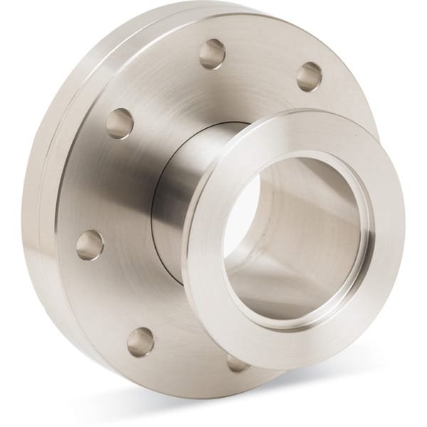
CF to KF adapter flanges are precision-machined vacuum components that connect two widely used vacuum flange standards. On one side, the adapter includes a CF flange interface, which utilizes a knife-edge sealing surface and a copper gasket to create an ultra-high vacuum seal. On the opposite side, the adapter provides a KF (QF) interface, which uses an elastomer O-ring and clamp connection for rapid assembly and disassembly.
The CF flange system is widely used in UHV environments because it provides extremely low leak rates and excellent resistance to high temperatures and vacuum cycling. However, CF connections typically require bolts and copper gaskets, making installation more time-consuming. KF fittings, in contrast, are designed for quick assembly using a clamp and centering ring, making them ideal for frequently reconfigured vacuum systems.
A CF to KF adapter flange bridges these two connection standards, enabling vacuum engineers to integrate components such as pumps, gauges, valves, viewports, and chambers that may use different flange formats. This is particularly useful when connecting high-vacuum pumping systems or diagnostic instruments to ultra-high vacuum chambers.
These adapters are usually manufactured from 304 or 316L stainless steel, which offers excellent corrosion resistance, mechanical strength, and vacuum compatibility. Precision machining ensures accurate flange dimensions and smooth sealing surfaces, which are critical for maintaining vacuum integrity.
Depending on system requirements, CF to KF adapters are available in various configurations, such as CF16 to KF16, CF35 to KF25, CF63 to KF40, and other combinations. Custom sizes and special designs can also be produced to match specific vacuum equipment layouts.
Applications
CF to KF adapter flanges are widely used in vacuum systems where different flange standards must be integrated. Typical applications include:
Ultra-high vacuum (UHV) research systems
Semiconductor and thin film deposition equipment
Mass spectrometry and analytical instruments
Particle accelerators and scientific research facilities
Vacuum pump connections and foreline systems
Laboratory vacuum setups requiring flexible connections
These adapters allow engineers to combine the reliability of CF flanges with the convenience of KF quick-clamp connections.
Technical Parameters
| Parameter | Typical Value / Range | Importance |
|---|---|---|
| Material | 304 / 316L Stainless Steel | Ensures vacuum compatibility and corrosion resistance |
| CF Flange Standard | CF16 – CF160 (various sizes) | Provides ultra-high vacuum metal seal |
| KF Flange Standard | KF10 – KF50 (NW sizes) | Enables quick clamp connections |
| Surface Finish | Precision machined sealing surfaces | Maintains vacuum integrity |
| Leak Rate | ≤ 1 × 10⁻¹⁰ mbar·L/s | Suitable for UHV systems |
| Temperature Range | Up to ~450 °C (CF side) | Compatible with UHV bakeout processes |
Comparison with Related Materials
| Component | Key Advantage | Typical Application |
|---|---|---|
| CF to KF Adapter Flange | Connects UHV CF systems to KF quick-clamp fittings | Vacuum system integration |
| CF to ISO Adapter | Links UHV systems to large high-vacuum pipelines | Industrial vacuum chambers |
| KF Tee / Cross | Allows branching of KF vacuum lines | Vacuum distribution systems |
| CF Flange | Ultra-high vacuum metal seal | UHV chambers and beamlines |
FAQ
| Question | Answer |
|---|---|
| What is the difference between CF and KF flanges? | CF flanges use metal gaskets for ultra-high vacuum sealing, while KF flanges use elastomer O-rings and quick clamps for high-vacuum applications. |
| Why use a CF to KF adapter? | It allows components with different flange standards to be connected in the same vacuum system. |
| What materials are typically used for these adapters? | Most adapters are made from 304 or 316L stainless steel for durability and vacuum compatibility. |
| Can the adapters withstand UHV bakeout temperatures? | The CF side can handle high bakeout temperatures, but the KF side is limited by the elastomer O-ring. |
| Are custom sizes available? | Yes, custom CF and KF combinations can be manufactured according to system requirements. |
Packaging
Our CF to KF (QF) Adapter Flanges are meticulously tagged and labeled externally to ensure efficient identification and maintain high standards of quality control. We take great care to prevent any potential damage during storage and transportation, ensuring the targets arrive in perfect condition.
Conclusion
CF to KF (QF) Adapter Flanges provide a practical and reliable solution for connecting ultra-high vacuum CF systems with high-vacuum KF quick-clamp components. Their precision machining, vacuum-compatible materials, and flexible size options make them essential components in modern vacuum engineering.
Whether used in research laboratories, semiconductor equipment, or industrial vacuum systems, these adapters help simplify system integration while maintaining excellent vacuum performance.
For detailed specifications and a quotation, please contact us at sales@thinfilmmaterials.com.
Ordering Table
| Flange Size/OD | Drawing | Nominal Tube OD | Flange Adapter | Dim A | Part Number |
| DN16CF (1.33" OD) |

| 3/4 | KF16 | 1.75 | F0133XQF16 |
| DN16CF (1.33" OD) |
| 3/4 | KF25 | 1.62 | F0133XQF25 |
| DN35CF-DN40CF (2.75" OD) |
| 3/4 | KF16 | 1.79 | F0275XQF16 |
| DN35CF-DN40CF (2.75" OD) |
| 1 | KF25 | 1.79 | F0275XQF25 |
| DN35CF-DN40CF (2.75" OD) |
| 1-1/2 | KF40 | 1.79 | F0275XQF40 |
| DN35CF-DN40CF (2.75" OD) |
| 1-3/4 | KF40 | 2.19 | F0275XQF40LB |
| DN50CF (3.38" OD) |
| 1-1/2 | KF40 | 1.8 | F0337XQF40 |
| DN63CF (4.50" OD) |
| 1-1/2 | KF40 | 1.95 | F0450XQF40 |
| DN63CF (4.50" OD) |
| 2 | KF50 | 1.95 | F0450XQF50 |
| DN16CF (1.33" OD) |
| 3/4 | KF40 | 1.62 | F0133XQF40 |
| DN16CF (1.33" OD) |
| 3/4 | KF50 | 1.62 | F0133XQF50 |
| DN35CF-DN40CF (2.75" OD) |
| 1-1/2 | KF50 | 1.79 | F0275XQF50 |
| DN63CF (4.50" OD) |
| 1 | KF25 | 1.95 | F0450XQF25 |
| DN100CF (6.00" OD) |
| 3/4 | KF16 | 1.95 | F0600XQF16 |
| DN100CF (6.00" OD) |
| 1 | KF25 | 2.01 | F0600XQF25 |
| DN100CF (6.00" OD) |
| 1-1/2 | KF40 | 2.02 | F0600XQF40 |
| DN100CF (6.00" OD) |
| 1-1/2 | KF50 | 2.02 | F0600XQF50 |
| DN160CF (8.00" OD) |
| 1 | KF25 | 2.08 | F0800XQF25 |
| DN160CF (8.00" OD) |
| 1-1/2 | KF40 | 2.08 | F0800XQF40 |
| DN160CF (8.00" OD) |
| 2 | KF50 | 2.08 | F0800XQF50 |

Reviews
There are no reviews yet.