TFM CF Flanges for High Vacuum and UHV Applications
The TFM CF (ConFlat) flange system is the preferred choice for high vacuum and ultra-high vacuum (UHV) applications. This widely used flange design accommodates a variety of gauges, instruments, accessories, and feedthroughs, making it highly versatile for various vacuum setups.
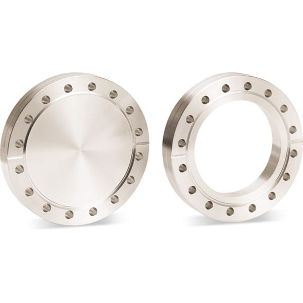
Understanding Blank (Blind) Flanges
A blank (or blind) flange functions as a solid, disc-shaped fitting in vacuum systems. Its primary purpose is to seal off unused tubing sections or ports on a vacuum chamber. These flanges can also be machined to create custom fittings tailored to specific needs.
Sealing Mechanism of TFM Flanges
The sealing mechanism of TFM flanges employs a knife-edge that is machined just below the flange’s flat surface. When the bolts of a flange pair are tightened, the knife-edges carve annular grooves into a soft metal gasket. This action allows the extruded metal to fill any surface imperfections and machining marks on the flange, resulting in a leak-tight seal. TFM seals operate effectively across a pressure range from 760 torr (103 mbar) to < 1 x 10^-13 Torr (< 1.3 x 10^-13 mbar) and can withstand temperatures from -196°C to 450°C, depending on the materials used.
Flange Size Nomenclature
In North America, TFM flange sizes are typically referenced by their outer diameter (O.D.), such as the 4.625-inch O.D. for the DN75CF. In contrast, European and Asian standards often refer to the nominal internal diameter (I.D.) of the largest tube that can be welded to a bored flange.
Available Versions of TFM Flanges
TFM offers four main configurations of flanges to suit different operational requirements:
Fixed Flange
The fixed flange features a one-piece design where the bolt-hole orientation is fixed relative to the fitting. This design is beneficial for applications requiring precise alignment.
Rotatable Flange
The rotatable flange consists of two parts: an inner weld ring and an outer bolt ring. This configuration allows the bolt ring to rotate around the inner weld ring, simplifying the alignment of the bolt holes during installation.
Both fixed and rotatable TFM flanges can be customized with your choice of through (clearance) holes or tapped holes, providing additional flexibility for various applications.
Applications of TFM CF Flanges
The robust sealing capabilities and versatility of TFM flanges make them ideal for numerous industries that require high or ultra-high vacuum conditions. They are essential components in sectors such as semiconductor manufacturing, materials research, and scientific instrumentation, where maintaining optimal vacuum integrity is crucial for performance and reliability.
Through (Clearance) Holes

Are through-holes that allow adequate clearance for bolts to go through both flanges and secured by nuts or plate nuts.
Tapped Holes

Are imperial or metric threaded holes machined through the flange. This allows a clearance-hole flange to be connected without the need for nuts or plate nuts. Be aware of a components bolt hole orientation when selecting tapped flanges.
Ordering Table
| Flange Size/OD | Type | Flange Material | Part Number |
| DN100CF (6.00" OD) | Fixed | 304L SS | F0600X000N |
| DN100CF (6.00" OD) | Fixed Tapped | 304L SS | F0600X000NM |
| DN100CF (6.00" OD) | Fixed Tapped | 304L SS | F0600X000NT |
| DN100CF (6.00" OD) | Rotatable | 304L SS | F0600X000R |
| DN100CF (6.00" OD) | Rotatable Tapped | 304L SS | F0600X000RM |
| DN100CF (6.00" OD) | Rotatable Tapped | 304L SS | F0600X000RT |
| DN100CF (6.00" OD) | Fixed | 304L SS | F0600X400N |
| DN100CF (6.00" OD) | Fixed Tapped | 304L SS | F0600X400NM |
| DN100CF (6.00" OD) | Fixed Tapped | 304L SS | F0600X400NT |
| DN100CF (6.00" OD) | Rotatable | 304L SS | F0600X400R |
| DN100CF (6.00" OD) | Rotatable Tapped | 304L SS | F0600X400RM |
| DN100CF (6.00" OD) | Rotatable Tapped | 304L SS | F0600X400RT |
| DN100CF (6.00" OD) | Fixed | 304L SS | F0600X412N |
| DN100CF (6.00" OD) | Fixed Tapped | 304L SS | F0600X412NM |
| DN100CF (6.00" OD) | Rotatable Tapped | 304L SS | F0600X412RM |
| Flange Size/OD | Type | Flange Material | Part Number |


Reviews
There are no reviews yet.