Introduction
DN25CF (2.125″ OD) 316LN Stainless Steel Standard ConFlat® (CF) UHV Flanges are compact, precision vacuum interfaces designed for ultra-high-vacuum systems where reliable metal sealing and minimal footprint are essential. DN25CF flanges are widely used on instrumentation ports, gauges, feedthroughs, and small process connections in semiconductor, surface science, and research vacuum equipment.
Detailed Description
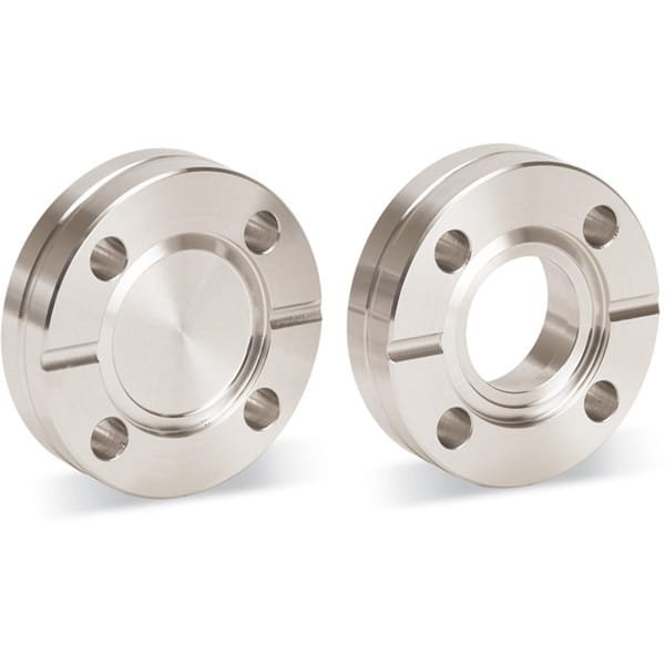
DN25CF flanges are precision-machined from vacuum-grade 316LN stainless steel, a low-carbon, nitrogen-strengthened alloy known for excellent corrosion resistance, mechanical strength, and very low outgassing. The accurately formed ConFlat® knife-edge geometry creates a dependable metal-to-metal seal when compressed against an OFHC copper gasket, ensuring consistent UHV performance even after repeated bakeout cycles.
With a 2.125 inch (54.0 mm) outer diameter, DN25CF flanges conform fully to international CF standards, allowing direct compatibility with elbows, tees, viewports, valves, and feedthroughs. The use of 316LN stainless steel provides enhanced rigidity and dimensional stability, which is especially beneficial for precision instruments and frequently cycled vacuum systems.
Applications
UHV gauges, viewports, and electrical feedthroughs
Semiconductor processing and analytical equipment
Thin film deposition systems (PVD, sputtering, evaporation)
Surface analysis tools (XPS, AES, UHV SEM interfaces)
Research and laboratory UHV vacuum manifolds
Technical Parameters
| Parameter | Typical Value / Range | Importance |
|---|---|---|
| Flange Type | ConFlat® (CF), DN25 | Standard UHV interface |
| Outer Diameter | 2.125″ (54.0 mm) | Compact system integration |
| Material | 316LN Stainless Steel | Low outgassing, high strength |
| Sealing Method | Knife-edge with copper gasket | Proven UHV metal seal |
| Bolt Pattern | DN25CF standard | Full CF compatibility |
| Bakeout Temperature | Up to ~450 °C | Suitable for UHV bake cycles |
| Leak Rate | ≤ 1×10⁻¹⁰ mbar·L/s (typical) | Maintains UHV integrity |
Comparison with Related CF Flanges
| Flange Size | Key Advantage | Typical Application |
|---|---|---|
| DN25CF (316LN SS) | Small footprint, UHV-rated | Instruments & feedthroughs |
| DN16CF | Ultra-compact | Miniature ports |
| DN40CF | Higher conductance | Diagnostics & pumping lines |
FAQ
| Question | Answer |
|---|---|
| Are copper gaskets included? | Copper gaskets are typically supplied separately unless requested. |
| Why choose 316LN over 304L for DN25CF? | 316LN offers higher strength and improved corrosion resistance. |
| Can DN25CF flanges be baked repeatedly? | Yes, they support repeated high-temperature UHV bakeouts. |
| Are electropolished versions available? | Yes, electropolishing can be provided on request. |
| How are knife edges protected during shipping? | Protective caps are used to prevent damage. |
Packaging
Our DN25CF 316LN SS Standard ConFlat® UHV Flanges are cleaned for vacuum service, with knife edges protected by caps. Each flange is individually packed using protective materials and shipped in export-grade cartons to ensure safe delivery and maintained surface quality.
Conclusion
DN25CF (2.125″ OD) 316LN SS Standard ConFlat® (CF) UHV Flanges provide compact size, exceptional sealing reliability, and full compatibility with global CF standards. Their robust construction and precision machining make them an ideal choice for high-performance UHV systems in semiconductor manufacturing, scientific research, and advanced vacuum applications.
For detailed specifications and a quotation, please contact us at sales@thinfilmmaterials.com.
Ordering Table
| Flange Size/OD | Type | Flange Material | Drawing | Part Number |
| DN25CF (2.13" OD) | Fixed | 316LN SS |

| F0212N000NLN |
| DN25CF (2.13" OD) | Fixed | 316LN SS |
| F0212N100NLN |


Reviews
There are no reviews yet.