Generic selectors
Exact matches only
Search in title
Search in content
Post Type Selectors

Hydraulically (Hydro) Formed Bellows – ISO Flanged (Braided Wall)

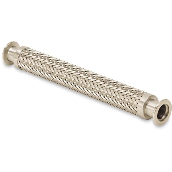
Fabrication of ISO Flanged Bellows for High Voltage Systems

TFM specializes in the production of ISO flanged formed bellows tailored for high voltage (HV) systems. These components are constructed using 300 series stainless steel flexible hoses in combination with 304L stainless steel ISO flanges. The ISO flange, often referred to as the Large ISO, is designed specifically for HV chamber ports and comes in two primary configurations: ISO-K, which utilizes clamp fasteners, and ISO-F, which employs nut and bolt fasteners.

Key Features of Hydroformed Bellows – ISO Flanged (Braided Wall)

  • Durability: Our flexible hoses are engineered to endure numerous flexing cycles, providing long-lasting performance without the risk of cracking.
  • Seam-Welded Design: The bellows are seam-welded to prevent virtual leaks commonly associated with lap-welded seams, ensuring a more reliable seal.
  • Flange Options: Available in the ISO-K style with clamp fasteners for ease of use.
  • Protection Features: The braided flexible hoses come with a protective sheath, safeguarding the convoluted hose against potential damage during operation.

TFM’s commitment to quality ensures that our products meet the rigorous demands of high voltage systems while providing enhanced durability and reliability.

Ordering Table

Drawing FlangeSize Length BellowsID Part Number
Tooltip 63 6 2.5 MHB-QF-E06
Tooltip 63 10 2.5 MHB-QF-E10
Tooltip 63 12 2.5 MHB-QF-E12
Tooltip 63 18 2.5 MHB-QF-E18
Tooltip 63 20 2.5 MHB-QF-E20
Tooltip 63 24 2.5 MHB-QF-E24
Tooltip 63 30 2.5 MHB-QF-E30
Tooltip 63 36 2.5 MHB-QF-E36
Tooltip 63 40 2.5 MHB-QF-E40
Tooltip 80 6 3 MHB-QF-F06
Tooltip 80 10 3 MHB-QF-F10
Tooltip 80 18 3 MHB-QF-F18
Tooltip 80 20 3 MHB-QF-F20
Tooltip 80 24 3 MHB-QF-F24
Tooltip 80 30 3 MHB-QF-F30
Tooltip 80 36 3 MHB-QF-F36
Tooltip 80 40 3 MHB-QF-F40
Tooltip 80 48 3 MHB-QF-F48
Tooltip 100 6 4 MHB-QF-G06
Tooltip 100 10 4 MHB-QF-G10
Tooltip 100 12 4 MHB-QF-G12
Tooltip 160 6 6 MHB-QF-H06
Tooltip 160 10 6 MHB-QF-H10
Tooltip 160 12 6 MHB-QF-H12

Reviews

There are no reviews yet.

Be the first to review “Hydraulically (Hydro) Formed Bellows – ISO Flanged (Braided Wall)”

Your email address will not be published. Required fields are marked *

FAQ

Tube fittings are designed for tubes (measured by outside diameter and wall thickness) used in high-pressure and instrumentation applications, whereas pipe fittings are for pipes (identified by nominal pipe size) primarily used in fluid transport.


Common valve types include ball valves, gate valves, check valves, butterfly valves, and globe valves. Each serves a specific function—from quick shutoff (ball/gate valves) to flow regulation (globe valves).

 
  • For tubing, measure the outside diameter; for pipes, refer to the nominal pipe size (using conversion charts if needed). Always match the valve or fitting size to your pipe’s dimensions and flow requirements.

  • Frequently used thread types include NPT (National Pipe Tapered), BSP (British Standard Pipe), and UNC, along with slip-fit options that rely on compression or fusion rather than threads.

Interchangeability depends on manufacturer specifications and certification. Always verify compatibility via manufacturer guides or certified interchangeability charts.

 
  • A coupling is a short, straight fitting used to join two pipes or tubes. It provides a secure, leak-tight connection and can sometimes serve to extend or repair piping runs.

Consider valve type, pressure and temperature ratings, material compatibility with your fluid, actuation method (manual or automatic), and maintenance requirements.

 
  • Valves regulate flow by opening, closing, or partially obstructing the pathway. Their mechanisms (such as the rotation of a ball or the linear movement of a gate) determine the speed and precision of flow control.

  • A flange is a flat, circular component used to connect pipes, valves, or other equipment. Bolted together with gaskets, flanges provide a secure, leak-proof joint that facilitates both assembly and maintenance.

  • Manual valves require physical operation via handles or levers, whereas actuated valves use mechanisms—pneumatic, electric, or hydraulic—to open and close automatically or remotely.

  • Issues include leaks caused by improper installation, over-tightening, degraded seals, material incompatibility, and fatigue from repeated cycling. Regular inspection and proper installation practices help mitigate these problems.

Regular maintenance involves periodic inspections, cleaning or replacing worn seals, ensuring proper torque during installation, and adhering to manufacturer guidelines and local plumbing codes to preserve system integrity.


Shopping Cart
Scroll to Top