Generic selectors
Exact matches only
Search in title
Search in content
Post Type Selectors

Hydraulically (Hydro) Formed Bellows – ISO Flanged (Standard Unbraided Wall)

Introduction to ISO Flanged Formed Bellows

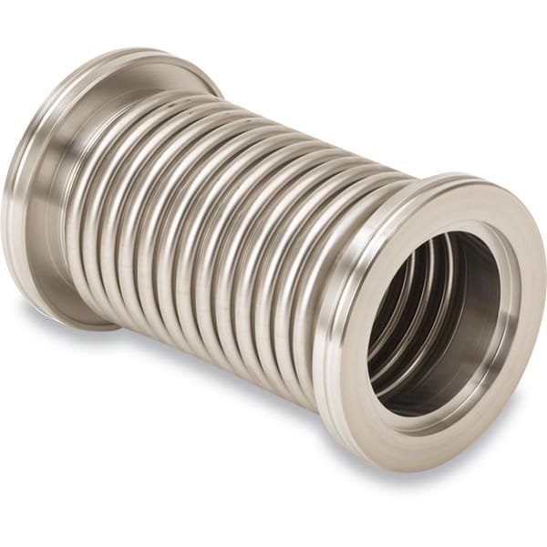
At TFM, we specialize in manufacturing ISO flanged formed bellows designed specifically for high vacuum (HV) systems. Our bellows are crafted from 300 series stainless steel flexible hoses and 304L stainless steel ISO flanges, ensuring durability and reliability in demanding environments.

Types of ISO Flanges

The ISO flanges, also known as Large ISO flanges, are available in two main styles for HV chamber ports:

  • ISO-K Flanges: These utilize clamp fasteners for secure connections.
  • ISO-F Flanges: These employ nut and bolt fasteners, offering a robust alternative.

Key Features of Hydro-Formed Bellows

Our hydraulically formed bellows feature several advantages:

  • Durability: Flexible hoses are engineered to endure numerous flexing cycles without risk of cracking.
  • Seam Integrity: Each bellows is seam-welded to minimize the potential for virtual leaks associated with lap-welded seams.
  • Flange Style: The standard unbraided wall design includes ISO-K (clamped) style flanges, making them suitable for various applications.
  • Flexibility: Unbraided flexible hoses can extend up to 10% beyond their live length and compress by up to 15%, providing excellent adaptability.
  • Protection: Our braided flexible hoses incorporate a protective sheath that safeguards the convoluted hose from damage, enhancing their longevity and performance.

By choosing TFM’s ISO flanged formed bellows, you benefit from high-quality materials and precise engineering tailored for HV systems.

Ordering Table

Hydraulically (Hydro) Formed Bellows - ISO Flanged (Standard Unbraided Wall)

Drawing FlangeSize Length BellowsID Part Number
Tooltip 63 6 2.5 MH-QF-E06
Tooltip 63 10 2.5 MH-QF-E10
Tooltip 63 12 2.5 MH-QF-E12
Tooltip 63 18 2.5 MH-QF-E18
Tooltip 63 20 2.5 MH-QF-E20
Tooltip 63 24 2.5 MH-QF-E24
Tooltip 63 30 2.5 MH-QF-E30
Tooltip 63 36 2.5 MH-QF-E36
Tooltip 63 40 2.5 MH-QF-E40
Tooltip 63 48 2.5 MH-QF-E48
Tooltip 80 6 3 MH-QF-F06
Tooltip 80 10 3 MH-QF-F10
Tooltip 80 12 3 MH-QF-F12
Tooltip 80 18 3 MH-QF-F18
Tooltip 80 20 3 MH-QF-F20
Tooltip 80 24 3 MH-QF-F24
Tooltip 80 30 3 MH-QF-F30
Tooltip 80 36 3 MH-QF-F36
Tooltip 80 40 3 MH-QF-F40
Tooltip 80 48 3 MH-QF-F48
Tooltip 100 6 4 MH-QF-G06
Tooltip 100 10 4 MH-QF-G10
Tooltip 100 12 4 MH-QF-G12
Tooltip 160 6 6 MH-QF-H06
Tooltip 160 10 6 MH-QF-H10
Tooltip 160 12 6 MH-QF-H12

Reviews

There are no reviews yet.

Be the first to review “Hydraulically (Hydro) Formed Bellows – ISO Flanged (Standard Unbraided Wall)”

Your email address will not be published. Required fields are marked *

FAQ

Tube fittings are designed for tubes (measured by outside diameter and wall thickness) used in high-pressure and instrumentation applications, whereas pipe fittings are for pipes (identified by nominal pipe size) primarily used in fluid transport.


Common valve types include ball valves, gate valves, check valves, butterfly valves, and globe valves. Each serves a specific function—from quick shutoff (ball/gate valves) to flow regulation (globe valves).

 
  • For tubing, measure the outside diameter; for pipes, refer to the nominal pipe size (using conversion charts if needed). Always match the valve or fitting size to your pipe’s dimensions and flow requirements.

  • Frequently used thread types include NPT (National Pipe Tapered), BSP (British Standard Pipe), and UNC, along with slip-fit options that rely on compression or fusion rather than threads.

Interchangeability depends on manufacturer specifications and certification. Always verify compatibility via manufacturer guides or certified interchangeability charts.

 
  • A coupling is a short, straight fitting used to join two pipes or tubes. It provides a secure, leak-tight connection and can sometimes serve to extend or repair piping runs.

Consider valve type, pressure and temperature ratings, material compatibility with your fluid, actuation method (manual or automatic), and maintenance requirements.

 
  • Valves regulate flow by opening, closing, or partially obstructing the pathway. Their mechanisms (such as the rotation of a ball or the linear movement of a gate) determine the speed and precision of flow control.

  • A flange is a flat, circular component used to connect pipes, valves, or other equipment. Bolted together with gaskets, flanges provide a secure, leak-proof joint that facilitates both assembly and maintenance.

  • Manual valves require physical operation via handles or levers, whereas actuated valves use mechanisms—pneumatic, electric, or hydraulic—to open and close automatically or remotely.

  • Issues include leaks caused by improper installation, over-tightening, degraded seals, material incompatibility, and fatigue from repeated cycling. Regular inspection and proper installation practices help mitigate these problems.

Regular maintenance involves periodic inspections, cleaning or replacing worn seals, ensuring proper torque during installation, and adhering to manufacturer guidelines and local plumbing codes to preserve system integrity.


Shopping Cart
Scroll to Top