Introduction
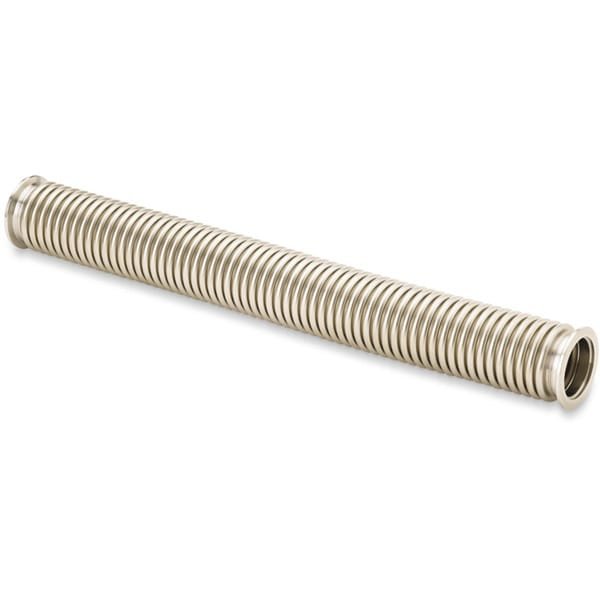
Hydraulically formed bellows with KF (QF) flanges and braided wall construction are essential components in high vacuum (HV) systems, designed to accommodate vibration, thermal expansion, and mechanical misalignment. These flexible connectors play a critical role in maintaining vacuum integrity while protecting sensitive equipment such as pumps, chambers, and measurement instruments from stress and vibration.
Detailed Description
Hydroformed bellows are manufactured through a precision hydraulic forming process, where seamless stainless steel tubes are expanded under high-pressure fluid to create uniform corrugations. This method produces bellows with superior structural integrity, consistent wall thickness, and enhanced fatigue resistance compared to mechanically formed alternatives.
The addition of an external braided wall (typically stainless steel braid) significantly improves the mechanical strength of the bellows. This reinforcement limits overextension, increases pressure resistance, and extends service life, especially in dynamic or vibration-prone environments. The braided design also provides additional protection against mechanical damage.
KF (QF) flanges—commonly used in high vacuum systems—enable quick and reliable connections using centering rings and clamps. These standardized connections allow for fast assembly and disassembly without compromising sealing performance, making them ideal for laboratory and industrial vacuum setups.
Constructed from high-quality stainless steel (304 or 316L), these bellows offer excellent corrosion resistance, low outgassing, and compatibility with a wide range of vacuum applications. Precision welding ensures leak-tight performance and long-term reliability under repeated thermal and mechanical cycling.
Applications
Hydraulically Formed Bellows – KF (QF) Flanged (Braided Wall) are widely used in:
- Vacuum Pump Connections: Isolating vibration between pumps and chambers
- Thin Film Deposition Systems: PVD, CVD, and evaporation equipment
- Semiconductor Manufacturing: Maintaining stable vacuum environments
- Analytical Instruments: Mass spectrometers and vacuum testing systems
- Industrial Vacuum Lines: Flexible connections in dynamic systems
Technical Parameters
| Parameter | Typical Value / Range | Importance |
|---|---|---|
| Material | 304 / 316L Stainless Steel | Corrosion resistance & low outgassing |
| Forming Method | Hydraulic (Hydroformed) | Uniform structure & high durability |
| Reinforcement | External Stainless Steel Braid | Enhances strength and limits extension |
| Flange Type | KF (QF) | Quick, standardized vacuum connection |
| Nominal Size | KF16 – KF100 (custom available) | Compatibility with HV systems |
| Pressure Range | Vacuum to slight positive pressure | Suitable for HV applications |
| Leak Rate | ≤ 1 × 10⁻⁹ mbar·L/s | Ensures vacuum integrity |
| Operating Temperature | Up to ~150–200°C | Depends on configuration |
Comparison with Related Components
| Component Type | Key Advantage | Typical Application |
|---|---|---|
| Hydroformed Bellows (Braided) | High strength, vibration resistance | Pump connections, dynamic systems |
| Hydroformed Bellows (Unbraided) | Greater flexibility | Static or low-stress connections |
| Formed Bellows (Mechanical) | Lower cost | Less demanding applications |
| CF Bellows Assemblies | UHV compatibility | Ultra-high vacuum systems |
FAQ
| Question | Answer |
|---|---|
| What is the advantage of hydroforming? | It produces uniform, seamless bellows with better fatigue resistance and durability. |
| Why use a braided wall design? | The braid reinforces the bellows, preventing overextension and improving mechanical strength. |
| Are KF connections easy to install? | Yes, KF (QF) flanges allow quick assembly using clamps and centering rings. |
| Can sizes and lengths be customized? | Yes, various diameters, lengths, and configurations can be tailored to your system. |
| Are these bellows suitable for UHV? | They are primarily designed for HV systems; UHV applications typically require CF flanged components. |
Packaging
Our Hydraulically (Hydro) Formed Bellows – KF (QF) Flanged (Braided Wall) are meticulously tagged and labeled externally to ensure efficient identification and maintain high standards of quality control. We take great care to prevent any potential damage during storage and transportation, ensuring the components arrive in perfect condition.
Conclusion
Hydraulically formed bellows with KF flanges and braided wall construction provide a reliable and durable solution for flexible vacuum connections. With excellent vibration isolation, mechanical strength, and ease of installation, they are ideal for a wide range of high vacuum applications.
For detailed specifications and a quotation, please contact us at sales@thinfilmmaterials.com.

Reviews
There are no reviews yet.