
KF (QF) HV Conical Reducer Nipples (304L SS): Tapered Stainless Steel Connectors for KF Flange Transitions in HV Systems
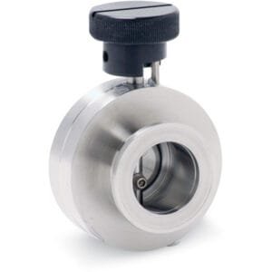
The KF (QF) HV Conical Reducer Nipples (304L SS) from TFM are engineered to provide smooth, tapered transitions between different KF flange sizes within high vacuum systems. Featuring a conical geometry, these reducer nipples are designed to optimize gas flow while maintaining axial alignment and structural integrity. Each unit is manufactured from 304L stainless steel, a vacuum-compatible alloy known for its corrosion resistance and thermal stability.
Whether you’re integrating components with different flange sizes or reconfiguring a foreline path, KF (QF) HV Conical Reducer Nipples (304L SS) offer a reliable and compact solution for managing vacuum connections.
Key Features of KF (QF) HV Conical Reducer Nipples (304L SS):
Conical Geometry for Flow Optimization
The tapered internal design of these nipples reduces turbulence and pressure drop, ideal for maintaining system efficiency across flange transitions.Dual KF Flange Interfaces
Each nipple connects two different KF (QF) flange sizes—such as KF40 to KF25—using standard centering rings and clamps for quick, tool-free assembly.304L Stainless Steel Construction
These KF (QF) HV Conical Reducer Nipples (304L SS) are built for durability and UHV compatibility, making them suitable for demanding scientific and industrial environments.High Vacuum Performance
Rated for use in systems operating down to 10⁻⁷ torr, these reducer nipples maintain leak-tight performance when used with proper sealing hardware.Standard and Custom Configurations
TFM provides a range of common flange combinations and lengths, and can manufacture custom KF (QF) HV Conical Reducer Nipples (304L SS) to meet specific application requirements.
Applications:
Transitioning between mismatched KF flanges in HV plumbing
Connecting pumps, gauges, or chambers with different port sizes
Reducing line diameter while maintaining consistent vacuum flow
Integrating sensitive instruments into tapered foreline designs
Supporting modular and retrofitted vacuum setups with high sealing reliability
TFM offers a comprehensive selection of KF components, including straight and conical reducer nipples, half and full nipples, and all required sealing accessories. Whether you’re assembling a new system or modifying an existing one, KF (QF) HV Conical Reducer Nipples (304L SS) ensure dependable and efficient performance.
Ordering Table
| Flange Size/OD (Large) | Flange Size/OD (Small) | Type | Flange Material | Drawing | Bore | Overall Length | Part Number |
| KF25 (1.57" OD) | KF16 (1.18" OD) | Reducing Nipple, Conical | 304L SS |

| 0.63 | 1.57 | QF25XQF16C |
| KF40 (2.16" OD) | KF16 (1.18" OD) | Reducing Nipple, Conical | 304L SS |

| 0.63 | 1.57 | QF40XQF16C |
| KF40 (2.16" OD) | KF25 (1.57" OD) | Reducing Nipple, Conical | 304L SS |

| 0.88 | 1.57 | QF40XQF25C |
| KF50 (2.95" OD) | KF16 (1.18" OD) | Reducing Nipple, Conical | 304L SS |

| 0.63 | 1.57 | QF50XQF16C |
| KF50 (2.95" OD) | KF25 (1.57" OD) | Reducing Nipple, Conical | 304L SS |

| 0.88 | 1.57 | QF50XQF25C |
| KF50 (2.95" OD) | KF40 (2.16" OD) | Reducing Nipple, Conical | 304L SS |

| 1.63 | 1.57 | QF50XQF40C |
Accessories Table
| Description | For | Per Package | Part Number |
| Cast Clamps (SS) | KF10, KF16 Flanges | 1 | QF16-075-CS |
| Cast Clamps (SS) | KF25 Flanges | 1 | QF25-100-CS |
| Cast Clamps (SS) | KF40 Flanges | 1 | QF40-150-CS |
| Cast Clamps (SS) | KF50 Flanges | 1 | QF50-200-CS |
| Cast Clamps (Aluminum) | KF10, KF16 Flanges | 1 | QF16-075-C |
| Cast Clamps (Aluminum) | KF25 Flanges | 1 | QF25-100-C |
| Cast Clamps (Aluminum) | KF40 Flanges | 1 | QF40-150-C |
| Cast Clamps (Aluminum) | KF50 Flanges | 1 | QF50-200-C |
| Lever Clamps (Aluminum) | KF10, KF16 Flanges | 1 | QF16-075-CHA |
| Lever Clamps (Aluminum) | KF25 Flanges | 1 | QF25-100-CHA |
| Lever Clamps (Aluminum) | KF40 Flanges | 1 | QF40-150-CHA |
| Centering Ring (SS with Fluorocarbon O-Ring) | KF10 Flanges | 1 | QF10-050-SRV |
| Centering Ring (SS with Fluorocarbon O-Ring) | KF16 Flanges | 1 | QF16-075-SRV |
| Centering Ring (SS with Fluorocarbon O-Ring) | KF25 Flanges | 1 | QF25-100-SRV |
| Centering Ring (SS with Fluorocarbon O-Ring) | KF40 Flanges | 1 | QF40-150-SRV |
| Centering Ring (SS with Fluorocarbon O-Ring) | KF50 Flanges | 1 | QF50-200-SRV |


Reviews
There are no reviews yet.