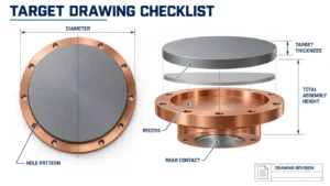
Quick answer: A useful sputtering target drawing should define more than diameter and target thickness. It should identify the target material and shape, critical dimensions and tolerances, edge and surface requirements, backing plate or carrier, bonding scope, total assembly height, mounting features, rear cathode-contact geometry, cooling-related interfaces, units, datums, drawing revision, and the inspection evidence required for acceptance. The drawing must match the actual sputtering source; a “standard” target size is not proof of cathode compatibility.
Why Material Diameter and Thickness Are Not Enough
An RFQ that says “aluminum target, 100 mm diameter, 6 mm thick” identifies a material and an approximate form. It does not establish whether the part will install correctly, maintain the intended clamping or rear contact, clear the shield, preserve the required target-to-magnet geometry, or fit the cathode after a backing plate and bond layer are added.
The same nominal target size can be used with different recesses, keepers, hole patterns, backing plates, installed heights, edge details, and source-specific interfaces. Commercial request forms therefore ask not only for target shape and size but also for backing-plate geometry, bonding, source manufacturer, and supporting drawings. Cathode manufacturers likewise use approval drawings to confirm fit before a design is released for manufacturing.
The purpose of the drawing is to turn “approximately right” into a measurable interface. It should show which dimensions control installation and which characteristics will be inspected.
Start With the Sputtering Source
Before drawing the target, identify the cathode or sputtering source. Provide the manufacturer and model when available, together with the source drawing, an existing approved target drawing, or an inspected sample assembly. Photographs help identify the general configuration, but they cannot establish hidden recesses, thread specifications, flatness, installed height, or tolerances.
Confirm whether the source uses direct clamping, a keeper ring, screws, a bonded backing plate, a cup, a backing tube, end blocks, or another mounting arrangement. Also identify the cooling path and the surface that contacts the cathode. These details determine which dimensions are functional rather than merely descriptive.
Separate the Target Backing Plate and Finished Assembly
A bonded target drawing should not collapse every layer into one thickness value. Define the components separately:
- Target: the sputtered material, with its own material identity, dimensions, edge details, and surface requirements.
- Bond layer: the specified or supplier-reviewed joining system and any agreed inspection requirement.
- Backing plate or carrier: the structural and thermal interface, including its material, geometry, mounting features, and rear contact.
- Finished assembly: the total installed geometry after bonding, including overall height and interface-critical features.
This separation prevents a supplier from interpreting “6 mm thick” as target-only thickness when the buyer intended total assembly thickness, or vice versa.
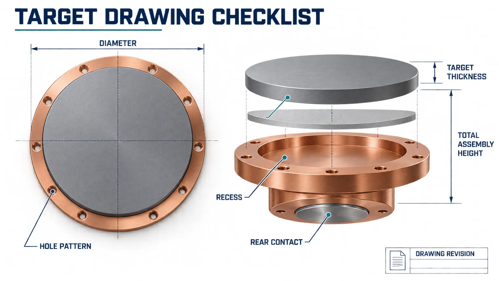
Circular Planar Target Drawing Checklist
| Drawing item | What to define | Why it matters |
|---|---|---|
| Target diameter | Finished diameter and tolerance | Controls fit, clamp engagement, and shield clearance |
| Target thickness | Target-only thickness, separate from backing and bond | Affects usable material, heat path, and installed geometry |
| Edge geometry | Square edge, radius, chamfer, step, or drawing-defined profile | Can affect clamping, handling, and local stress |
| Target-side surface | Surface finish or condition only where required | Provides an inspectable requirement without assuming one universal finish |
| Backing plate | Material, diameter, thickness, recess, and plate-specific features | Controls support, heat transfer, mounting, and cathode fit |
| Total assembly height | Finished bonded height with tolerance | Protects the installed relationship between target, clamp, shield, and magnet |
| Hole pattern | Quantity, size, position, pitch-circle diameter, counterbore, countersink, or thread | Prevents a nominally correct disc from being impossible to mount |
| Rear contact | Contact diameter, step, recess, flat, groove, or other source interface | Controls seating and the thermal path to the cathode |
| Keeper or retaining features | Keeper material, geometry, fasteners, and orientation where applicable | Defines assembly retention and source-specific fit |
| Orientation | Reference mark or clocking requirement when features are not symmetric | Prevents incorrect rotational installation |
Rectangular and Linear Target Drawings
Rectangular and linear targets need length, width, and thickness, but the useful drawing usually goes further. Identify corner radii or chamfers, edge steps, backing dimensions, bolt or clamp zones, datum edges, feature orientation, total assembly height, rear contact, and any segmented construction.
For long targets, do not rely on one overall length to communicate straightness, flatness, bow, or the location of mounting features. If those characteristics are functionally important, define them with the appropriate datum scheme and inspection method. Avoid adding a tight tolerance simply because it looks precise; specify it because the source or process requires it and because it can be inspected.
Rotary Target and Backing Tube Drawings
A rotary target RFQ should distinguish the target material from the backing tube and end interfaces. Depending on the source design, the drawing may need to define target outside diameter, target length, target-layer thickness, backing-tube material and dimensions, exposed end lengths, end-block interfaces, sealing or groove features, journal or flange geometry, concentricity, straightness, runout, orientation, and the finished assembly length.
These are source-specific requirements. Do not transfer dimensions from another rotary cathode merely because the nominal tube diameter appears similar. Use the source-owner drawing or an approved assembly record as the interface authority.
Bonding and Backing Plate Information
When bonding is required, state whether the buyer is specifying a method or asking the supplier to review the assembly. Include the target and backing materials, target and backing dimensions, total assembly height, recess or step geometry, operating context, cooling arrangement, and any agreed bond inspection.
Do not assign one universal bond-line thickness, operating temperature, bond-coverage threshold, or backing material to every target. Those values depend on the target material, assembly size, bonding system, source design, heat load, thermal expansion, and acceptance plan. For assembly selection, use the Bonded vs Unbonded Sputtering Targets guide and the TFM Bonding and Backing Plate Service.
How to Define Tolerances Without Over-Specifying
Every tolerance should protect a function, inspection decision, or interface. Use tighter tolerances for dimensions that control cathode fit, rear contact, installed height, hole location, sealing, or critical alignment. Use appropriate general tolerances for noncritical features.
- State units clearly and do not mix millimetres and inches without an explicit conversion basis.
- Identify datums so hole positions, recesses, steps, and rear-contact features are measured from the intended reference.
- Distinguish dimensional tolerance from surface finish, flatness, parallelism, concentricity, or runout.
- State whether dimensions apply before or after bonding, coating, plating, resurfacing, or another finishing operation.
- Confirm that the proposed inspection method can verify the requirement.
If a tolerance has no known functional reason, discuss it before quotation. Unnecessary precision can increase cost or create a rejection criterion without improving cathode compatibility.
Material and Surface Notes Belong on the Drawing or Specification
The drawing should identify each component, but chemistry and quality requirements may be better controlled in a linked material specification. State the target material or composition, purity basis, named impurity limits when required, backing material, keeper or fastener material, and any required plating or surface preparation. Reference the applicable specification and revision rather than placing ambiguous notes such as “high purity” or “standard finish.”
Material identity does not prove film performance. The purchase requirement should distinguish target acceptance evidence from the customer’s process and film-qualification plan.
Drawing Revision and Change Control
Give every controlled drawing a number, revision, date, units, and approval status. The quotation, purchase order, supplier acknowledgment, inspection report, and packaging label should refer to the same revision where project controls require it.
When a change is made, identify what changed and whether existing inventory, tooling, or customer-supplied backing plates remain compatible. A revised hole location or total height can be more consequential than a material note even if the target diameter is unchanged.
Inspection Evidence to Request
| Evidence | What it should connect to |
|---|---|
| Dimensional inspection report | Drawing number, revision, measured characteristics, units, tolerance, and part or lot identity |
| Material or composition record | Target or backing component identity and the agreed specification basis |
| Bonding inspection | Finished assembly identity, agreed method, coverage or discontinuity criteria when specified |
| Photographic record | Part identity, front, rear, edge, mounting features, and packaged condition as agreed |
| Packaging and labeling record | Part number, revision, handling protection, and traceability requirements |
Ask for evidence that supports the purchase requirement. Do not request a certificate, measurement, or acceptance claim that has not been defined.
Common RFQ Drawing Mistakes
- Providing target diameter and thickness but omitting the cathode model or interface drawing.
- Using one thickness value without stating whether it is target-only or total assembly height.
- Showing holes without thread, counterbore, countersink, depth, position, or datum information.
- Copying a “standard” backing plate from another source without verifying rear contact and installed height.
- Specifying tight tolerances on every dimension but omitting the functional flatness, contact, or alignment requirement.
- Sending an obsolete drawing revision or allowing the quotation and purchase order to reference different revisions.
- Assuming a photo can replace a measured drawing for a custom or OEM-source assembly.
Copyable Sputtering Target Drawing RFQ Checklist
- Target material or composition, purity basis, and named impurity requirements.
- Planar circular, rectangular, rotary, segmented, or other geometry.
- Target-only dimensions, tolerances, edge profile, and required surface condition.
- Backing plate, carrier, backing tube, keeper, and fastener materials and dimensions.
- Bonded or unbonded construction; bonding method if specified or request for supplier review.
- Total finished assembly height or length.
- Recesses, steps, grooves, holes, threads, pitch-circle diameter, and feature orientation.
- Rear cathode-contact and cooling-related interfaces.
- Cathode or source manufacturer, model, and approved interface drawing.
- Units, datums, general tolerances, functional geometric controls, and drawing revision.
- Required dimensional, material, bonding, photographic, labeling, and packaging evidence.
- Quantity, customer-supplied components, delivery destination, and requested schedule for quotation review.
Frequently Asked Questions
Can I order a sputtering target without a drawing?
A simple unbonded catalog geometry may be quotable from a complete dimensional description, but a drawing is strongly preferred for custom targets, bonded assemblies, backing plates, source-specific interfaces, hole patterns, recesses, or controlled tolerances.
Is the cathode model enough to define the target?
Not always. Equipment may have revisions, custom modifications, alternative clamps, or legacy assemblies. Confirm the source model together with the applicable drawing or measured interface.
Should the bond layer be included in total assembly height?
The finished assembly requirement should make clear what is included. Define target-only thickness, backing thickness, and total bonded height separately so the interpretation is unambiguous.
Can TFM review an existing target or backing plate?
TFM can review available drawings, photos, source information, and customer-supplied components for quotation feasibility. A physical sample may support measurement, but final requirements and acceptance criteria must be confirmed in the approved drawing and quotation.
Send a Drawing for Technical Review
Browse the TFM Sputtering Targets catalog, compare planar and rotary target configurations, or send the target drawing, cathode model, material requirement, quantity, and inspection scope for review. TFM will confirm feasibility and the final specification through the quotation process.
Technical References
- Kurt J. Lesker Company, Sputter Target Material Request.
- Angstrom Sciences, Magnetron Sputtering Cathode Design.
- Angstrom Sciences, Linear Magnetron Outline Drawings.
- TFM, Sputtering Target Bonding and Backing Plate Services.