Introductio
In the realm of thin film deposition, achieving consistent coating quality across a substrate is a mission-critical goal. For processes like magnetron sputtering, the uniformity of the deposited film is profoundly influenced by the erosion profile of the sputtering target. But what exactly is the erosion profile? Why does it matter? And how can engineers and scientists control it to improve deposition uniformity?
This article takes a deep dive into how sputtering target erosion profiles are formed, what factors influence them, and how they relate directly to thin film deposition outcomes. We’ll explore practical engineering strategies to manage these variables and maintain stable performance throughout target life. Along the way, we’ll naturally integrate relevant search keywords to help readers—especially those searching on Google—find exactly what they need.
What Is Sputtering Target Erosion?
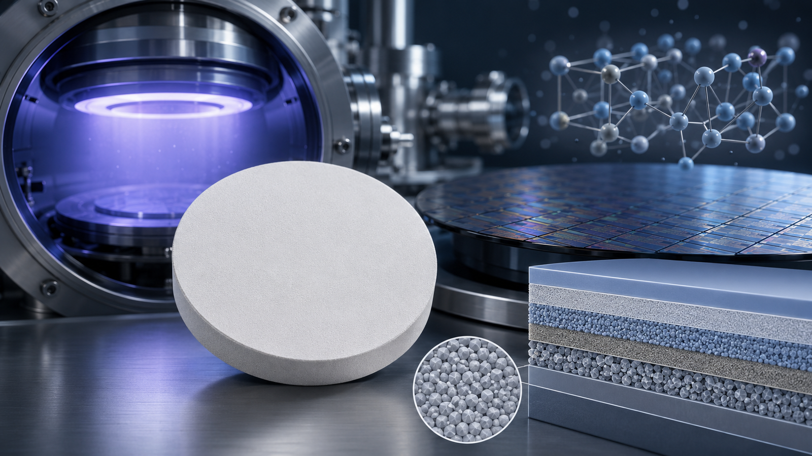
At its core, sputtering is a physical vapor deposition (PVD) technique that uses high-energy ions to dislodge atoms from a solid target material. These atoms then travel through a vacuum chamber and deposit onto a substrate, forming a thin film. However, this process does not uniformly remove material from the target surface.
The erosion profile refers to the spatial pattern and depth of material removal that develops on the surface of the sputtering target over time. As the target is bombarded with ions (typically argon ions), certain areas receive more energy than others, leading to non-uniform wear.
This wear pattern matters because the position and shape of the erosion zone dictate the angular distribution of sputtered atoms. Consequently, it directly influences how uniformly the coating is deposited on the substrate.
The Link Between Erosion Profiles and Deposition Uniformity
Understanding how erosion profiles affect film uniformity is central to achieving reliable thin film coatings, particularly in industries like semiconductors, optics, and photovoltaics.
When a target erodes unevenly, the flux of sputtered atoms across the substrate becomes inconsistent. This can result in:
- Thickness gradients across the wafer or panel
- Defects and pinholes in critical areas
- Compositional non-uniformity (especially in co-sputtering or alloy targets)
- Reduced device yield and functionality
This is why managing erosion profiles is not just an academic concern—it’s a production imperative.
Factors Influencing Sputtering Target Erosion Profiles
Let’s explore the primary variables that shape the erosion profile of a sputtering target:
1. Magnetic Field Configuration (Magnetron Design)
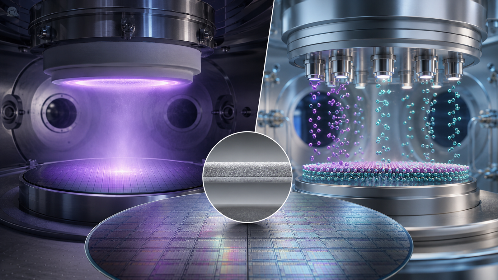
In magnetron sputtering systems, magnets placed behind the target generate magnetic field lines that confine electrons close to the target surface. This boosts ionization efficiency and sputtering rates.
However, the shape and intensity of the magnetic field also control where ion bombardment is most intense, leading to characteristic erosion patterns such as:
- Racetrack erosion: A donut-shaped groove that forms under a circular magnet array.
- Spoke-shaped or crescent erosion: Caused by asymmetric or rotating magnet arrangements.
By adjusting magnet strength and position, engineers can alter the erosion profile to improve deposition uniformity.
2. Target Thickness and Material Properties
The physical properties of the target material—such as thermal conductivity, atomic mass, and mechanical strength—also influence erosion behavior. Softer materials may erode more quickly, while brittle materials can crack under stress.
Thicker targets last longer but may suffer from uneven erosion if magnet placement isn’t optimized. In contrast, thinner targets can heat up more rapidly and exhibit non-linear erosion rates.
3. Power Mode (DC vs RF vs Pulsed DC)
The power mode used in sputtering significantly affects ion energy and plasma distribution:
- DC sputtering is common for conductive targets and tends to produce more stable erosion zones.
- RF sputtering is used for insulating targets but may yield broader erosion patterns due to lower ion densities.
- Pulsed DC sputtering helps reduce arcing and stabilize erosion on complex targets.
These modes change the energy profile across the target, altering the spatial erosion dynamics.
4. Working Pressure and Gas Flow
The argon gas pressure inside the chamber affects ion mean free path and scattering behavior. At lower pressures, ions travel in straight lines, creating sharper, localized erosion. At higher pressures, increased scattering leads to broader, more diffuse erosion profiles.
Non-uniform gas flow can also cause asymmetries in plasma density, resulting in off-centered erosion rings.
5. Target-to-Substrate Distance
The distance between the target and substrate alters the angular distribution of sputtered atoms. A closer distance enhances deposition rates but can exaggerate the effect of uneven erosion. Larger distances may improve uniformity by averaging out angular disparities but at the cost of deposition rate.
6. Target Utilization and Rotation
Target rotation (or rotating magnetrons) is commonly used in large-area sputtering systems to prolong target life and even out erosion. Without rotation, stationary erosion zones deepen faster, leading to premature failure and poor uniformity.
Mapping and Measuring Erosion Profiles
To effectively manage erosion, you first need to measure it. Here are common techniques used in industry:
- Profilometry: Mechanical or optical profilometers scan the worn surface to create a 3D erosion map.
- Weight loss measurement: Weighing the target before and after use gives total material removed, though not spatial information.
- Cross-sectional microscopy: Provides detailed views of erosion trenches and subsurface microstructural changes.
- Simulation and modeling: Finite element models predict erosion patterns based on plasma density and magnetic field simulations.
Visualizing the erosion profile helps engineers determine when to stop a run, when to flip the target (in the case of double-sided use), or when to adjust deposition parameters.
Deposition Uniformity: What It Means and Why It Matters
Deposition uniformity is defined as the consistency of film thickness and composition across the entire substrate surface. For critical applications, uniformity better than ±2% is often required.
Inadequate uniformity leads to:
- Optical interference issues in filters and lenses
- Electrical inconsistencies in thin-film transistors (TFTs) and capacitors
- Reduced photovoltaic efficiency in solar cells
- Dielectric failure in semiconductors
The quality of the erosion profile is directly proportional to your ability to maintain such uniformity over time, especially as the target ages.
Strategies to Improve Deposition Uniformity via Erosion Control
1. Optimized Magnetron Design
Use magnet arrays that produce flat or tunable magnetic fields. In high-end systems, dynamic magnetron designs enable real-time field adjustments to adapt erosion patterns as the target wears.
2. Substrate Movement
By rotating or translating the substrate during deposition, one can average out angular disparities in sputtered flux, especially useful when targets exhibit racetrack erosion.
3. Use of Shielding and Masks
Custom-designed deposition shields and masks can help shape the angular flux reaching the substrate. These are often used in optical coating systems to correct non-uniform flux.
4. Feedback and Control Systems
Advanced PVD systems employ in-situ sensors, optical monitoring, and plasma characterization tools to adjust process parameters in real time, helping compensate for evolving erosion profiles.
5. Multi-Target Configurations
Using multiple targets (such as in dual magnetron sputtering or co-sputtering) allows fine control over film composition and flux uniformity, especially if each target has a distinct erosion pattern.
Real-World Application: Erosion Profile in Semiconductor Manufacturing
In the semiconductor industry, even minor deviations in thin film thickness—on the order of nanometers—can result in device failure. For example, a gate dielectric in a MOSFET must be precisely controlled for thickness to ensure correct voltage thresholds and minimal leakage.
Manufacturers rely on high-purity planar targets with engineered backing plates and tight magnet control to produce consistent erosion behavior. Erosion modeling is routinely conducted during process development to ensure layer uniformity across 200mm or 300mm wafers.
Challenges and Future Trends
While the science of erosion control has matured, emerging challenges persist:
- Next-generation displays and 3D electronics require ultra-uniform coatings on complex topographies.
- Green technologies, such as large-area solar panels and battery films, push demands for scale and uniformity.
- AI-powered process control is being explored to predict erosion changes and proactively adjust magnetron or chamber parameters.
Materials like ceramic sputtering targets, composite alloys, and rotating cylindrical targets are also gaining popularity to extend life and enhance uniformity.
Conclusion
Understanding the interplay between sputtering target erosion profiles and deposition uniformity is foundational for high-performance thin film manufacturing. From the shape of the magnetic field to the intricacies of gas flow, every variable matters—and they all influence the final film characteristics.
For process engineers, material scientists, and product designers, staying on top of erosion dynamics is a gateway to achieving high-yield, defect-free thin films that meet the stringent demands of today’s technologies.
As the industry evolves, so too must our approach to erosion modeling, target design, and deposition control. With precise strategies and smart engineering, the complex art of sputtering can become a predictable science.