Quick answer: Coating shrinkage is a reduction in film volume or in-plane dimensions during drying, curing, cooling, or later environmental exposure. In a wet-applied coating, solvent loss, capillary forces, binder consolidation, and chemical conversion can create contraction. If the substrate restrains that contraction, tensile stress may develop and contribute to cracking or loss of adhesion. A vacuum-deposited thin film can show similar defects, but its residual stress may instead come from film-growth processes, energetic particle bombardment, microstructure, or thermal-expansion mismatch. Identify the process class before changing a formulation or deposition recipe.
What Does “Coating Shrinkage” Mean?
The phrase is often used for two related but distinct problems:
- Wet-applied coating shrinkage: a liquid, slurry, ink, paint, varnish, sol-gel, or polymer layer loses volatile material, consolidates, or reacts as it becomes solid.
- Vacuum-deposited thin-film stress: a sputtered, evaporated, CVD, or ALD layer develops tensile or compressive residual stress during growth, cooling, or later exposure.
Both can produce curvature, cracking, delamination, or wrinkling, but the corrective variables are not interchangeable. This page owns the drying-and-curing shrinkage intent. For deposited-film mechanisms, use the separate guide to residual stress in vacuum-deposited thin films.
Why Does a Coating Shrink During Drying or Curing?
Solvent or water leaves the film
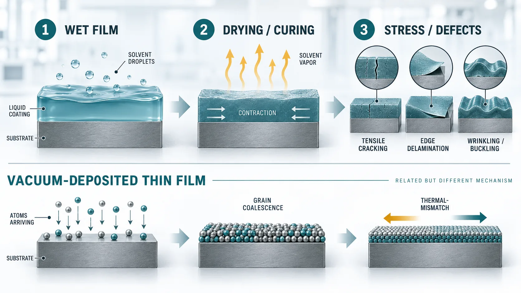
A wet coating contains a nonvolatile fraction and a volatile fraction. As water or solvent leaves, the remaining binder, particles, and additives occupy less volume. In particulate coatings, receding liquid menisci can create capillary pressure and pull the structure together. The final stress depends not only on how much liquid is lost, but also on when the coating becomes mechanically capable of retaining stress.
The binder consolidates or chemically converts
Polymer chains, particles, or reactive groups can rearrange and form a denser network during film formation. Crosslinking may add chemical shrinkage, but the relationship between conversion, modulus, solvent content, and final stress is system-specific. A faster cure is therefore not automatically worse, and a higher crosslink density is not automatically the dominant cause.
The substrate restrains free contraction
A free-standing film can contract. A bonded coating cannot contract freely in the plane of a rigid substrate, so part of that tendency can become tensile stress. Whether the film cracks or the interface separates depends on the evolving modulus, fracture resistance, adhesion, thickness, defect population, and substrate constraint—not shrinkage alone.
Drying is nonuniform through the thickness or across the part
Temperature, humidity, airflow, coating thickness, edge geometry, and local heat transfer can produce different drying histories. A surface that solidifies while deeper material still contains solvent can create a gradient in composition and mechanical properties. Local thickness variation may create stress concentrations, but the direction and severity must be established for the actual formulation and geometry.
Cooling or service exposure adds another stress source
A cure or bake performed above use temperature can be followed by thermal mismatch as the coating/substrate pair cools. Moisture uptake, solvent exposure, oxidation, or polymer degradation can later cause swelling, embrittlement, or renewed shrinkage. A defect observed after aging may therefore be a service-environment problem rather than a drying-only problem.
Coating Shrinkage Diagnostic Matrix
| Observation | Possible contributors | Evidence to collect | Controlled comparison |
|---|---|---|---|
| Mud cracking or tensile cracks | Drying stress, high constraint, thickness, low fracture resistance, local defects | Wet/dry thickness, mass loss, crack timing, microscopy, cure history | Compare one thickness or drying-profile variable at a time |
| Wrinkling or buckling | Compressive stress, skin formation, swelling, weak interface | Cross-section, surface profile, adhesion map, humidity/solvent history | Separate drying-stage behavior from later exposure |
| Edge lift or delamination | Interfacial contamination, poor wetting, residual stress, edge geometry | Substrate cleaning record, contact angle if relevant, failure surface, adhesion test | Use a documented surface-preparation control |
| Curling or substrate bow | Stress imbalance, one-sided coating, thermal mismatch, thickness gradient | Curvature before/after each stage, temperatures, substrate and film thickness | Measure after coat, dry, cure, cool, and conditioning |
| Thickness or dimension below target | Incorrect solids content, deposition/application volume, densification, metrology mismatch | Solids fraction, wet thickness, dry thickness, measurement method and locations | Close a mass/volume balance before changing cure conditions |
A Six-Step Troubleshooting Workflow
- Define the process. Record whether the layer is wet-applied, converted from a precursor, or vacuum-deposited. If more than one process is used, separate the stages.
- Define the failure precisely. Distinguish volume or thickness loss from cracking, interfacial separation, wrinkling, curl, and substrate bow.
- Build a time line. Note when the change first appears: during flash-off, drying, chemical cure, cooling, conditioning, or service exposure.
- Record a baseline. Capture formulation batch, solids content where applicable, wet and dry thickness, substrate, preparation, environment, temperature history, airflow, and measurement method.
- Change one mechanism-linked variable. Examples include a documented drying profile, thickness, substrate preparation, or formulation control. Do not combine several untracked changes and then assign a cause.
- Verify both stress and function. A visually smooth film is not proof of adequate adhesion, electrical performance, optical performance, or durability. Use acceptance tests that match the application.
How to Reduce Shrinkage-Related Defects
There is no universal solvent, additive, cure temperature, airflow setting, or layer thickness that prevents shrinkage across coating systems. The safe approach is to reduce the specific driving force or improve the film/interface tolerance after the mechanism is supported by evidence.
- Formulation: confirm solids content, solvent package, binder chemistry, filler or pigment loading, additive compatibility, and pot-life state with the formulation owner.
- Application: control wet thickness and uniformity, edge build, substrate cleanliness, and elapsed time between preparation and coating.
- Drying and cure: use the supplier-approved process window, record actual part temperature rather than only oven setpoint, and assess whether staged solvent removal or cure is compatible with the chemistry.
- Geometry and interface: inspect corners, steps, sharp edges, roughness transitions, and areas with different thermal mass. Improve adhesion only with a validated pretreatment or interface design.
- Measurement: compare mass, thickness, curvature, microscopy, and adhesion at defined process checkpoints. Where applicable, stress can be inferred from curvature only when the method assumptions and material properties are appropriate.
When the Problem Is a Vacuum-Deposited Thin Film
For sputtered or evaporated layers, “shrinkage” is often an imprecise description of residual stress, densification, phase change, or thermal mismatch. Published reviews show that deposited-film stress can be tensile or compressive and can vary strongly with the material system, deposition conditions, microstructure, thickness, substrate, and post-deposition thermal history. A single parameter rule cannot be transferred safely from one chamber and stack to another.
For a PVD investigation, record the target or source material, film/substrate stack, deposition method, gas and reactive-gas history, power mode, pressure, substrate temperature and bias, thickness, post-treatment, curvature or stress method, and defect images. TFM’s sputtering target and evaporation material pages can help identify the source-material category; they do not replace process qualification.
Information to Include in a Technical Inquiry
- Coating chemistry or deposited material, including the requested composition—not only a trade name
- Wet-applied or vacuum-deposited process and equipment type
- Substrate material, surface preparation, geometry, and size
- Wet and dry thickness targets and the measurement method
- Drying, cure, deposition, cooling, and post-treatment history
- Defect type, location, timing, images, and failed acceptance test
- Environmental or service exposure before the failure appeared
- The exact material, form, purity basis, dimensions, and documentation needed for a source-material RFQ
For source-material selection or a quotation, contact TFM with the applicable fields above. Do not infer a coating recipe from a target or evaporation-material specification alone.
Evidence Boundary
Evidence boundary: This guide provides a diagnostic framework, not a universal formulation or operating recipe. Shrinkage, stress, adhesion, fracture, and durability depend on the complete coating/substrate system and its process history. No thickness, temperature, humidity, airflow, solvent, additive, or deposition setting is recommended here without system-specific evidence and the relevant material and equipment instructions.
Technical References
- Gane et al., observation of shrinkage during evaporative drying of water-based paper coatings, Industrial & Engineering Chemistry Research.
- Modeling the drying of polymer coatings, Soft Matter.
- Curing-induced internal stress in epoxy coatings across formulation and environmental variables, Progress in Organic Coatings.
- Stress and embrittlement in organic coatings during weathering, Progress in Organic Coatings.
- Residual stresses in deposited thin-film layers for micro- and nano-systems, Micromachines.