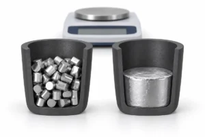
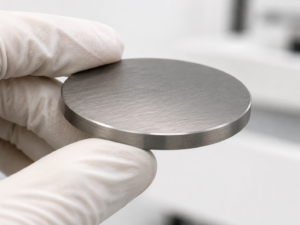
Evidence note: The public page contained photographs and operating values, but the repository did not contain the original customer correspondence, image provenance, tool logs, target inspection record, bond inspection, or a destructive failure analysis. The images are retained as field-observation examples; the root cause is not proven.
A cracked tantalum disilicide (TaSi₂) sputtering target is a system-level failure until evidence separates material condition, target geometry, backing and bond, cathode contact, clamping, cooling, plasma distribution, power history, and handling. A radial crack pattern can be consistent with thermomechanical stress, but a photograph alone cannot establish the initiating mechanism.
First Response: Stop and Preserve Evidence
- Stop operation and follow the tool’s safe shutdown and vent procedure.
- Do not continue sputtering a visibly cracked target unless the equipment and target suppliers provide written direction.
- Photograph the installed state before disturbing clamps, keeper rings, shims, or backing contacts.
- Save the complete run log: power mode, ramp, time, pressure, gas flow, arcs, reflected power if applicable, cooling data, interlocks, and shutdown events.
- Record target serial/batch, dimensions, backing and bond system, prior run history, conditioning, storage, and installation torque or procedure.
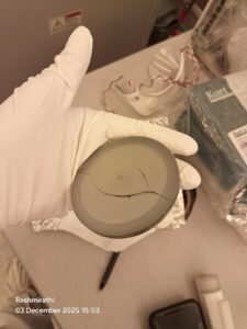
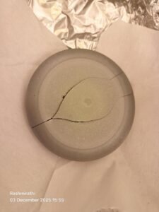
Separate Observations From Hypotheses
| Evidence | What it can support | What it cannot prove alone |
|---|---|---|
| Crack origin and path | Location and morphology to compare with loading or hot zones | Exact stress source or material defect |
| Installed photographs | Visible clamp, ring, debris, gap, or contact condition | Hidden bond integrity or cooling performance |
| Power/time log | Sequence, transient events, and repeatability | Actual target temperature without measurement/model |
| Cooling log | Inlet/outlet condition and interlock behavior | Uniform heat transfer across every interface |
| Pre/post inspection | Whether a defect was visible before use | Subsurface flaw population without suitable NDT |
Power Density Must Be Defined Correctly
Total watts are not transferable between cathodes or target sizes. At minimum, document target area and the equipment maker’s power-density convention; the active erosion area, magnetic field, plasma distribution, duty cycle, cooling, backing, bond, and target thickness may all change the thermal state. A nominal calculation using full face area is only a screening value—not proof of local heat flux.
The former article prescribed universal ramp and maximum-watt values. Those numbers have been removed because the available record did not show a validated safe operating envelope. Initial conditioning and operating limits must come from the cathode manufacturer, target supplier, and an application-specific risk review.
Failure Hypotheses to Test
Thermal transient or nonuniform heating
Compare crack position with the erosion track and any hot-zone evidence. Review the complete ramp, plasma ignition, arcs, interruptions, and cooling state. Do not infer temperature from power alone.
Mounting or keeper-ring stress
Check seating, particle contamination, backing flatness, clamp sequence, torque procedure, clearance, and contact marks. Confirm that retention hardware did not bridge, point-load, or constrain the assembly outside the qualified design.
Backing or bond condition
Inspect for voiding, separation, damage, or an out-of-scope operating temperature. The supplier should identify the backing and bond system, inspection method, and relevant limitations without implying that bonding eliminates fracture risk.
Target material or machining condition
Review chemistry, density measurement basis if specified, visible defects, edge condition, residual-stress controls if documented, and pre-shipment inspection. A certificate of composition does not prove freedom from every critical flaw.
Information Package for Supplier Review
- Target drawing, serial/batch, backing plate, bond, and keeper-ring details
- Cathode/tool model and manufacturer instructions
- As-installed, post-failure, fracture-face, backing, and hardware photographs
- Power mode, ramp, time, pressure, gas, arcs, cooling, and interlock logs
- Handling, cleaning, storage, installation, and conditioning history
- Any pre-use dimensional, visual, acoustic, radiographic, or other inspection record
Use the Tantalum Silicide Sputtering Target page for product/RFQ intent. For alternative target families, review the ceramic sputtering target category. Do not change material solely to address a fracture until the device and deposition requirements are reviewed.
Safe Restart Decision
A restart plan should have named owners, documented corrective actions, tool and target supplier agreement where required, and measurable stop conditions. It should define installation checks, conservative conditioning, monitoring, inspection intervals, and criteria for aborting the run. If the evidence is insufficient, label the cause “undetermined” and avoid presenting a preferred hypothesis as fact.