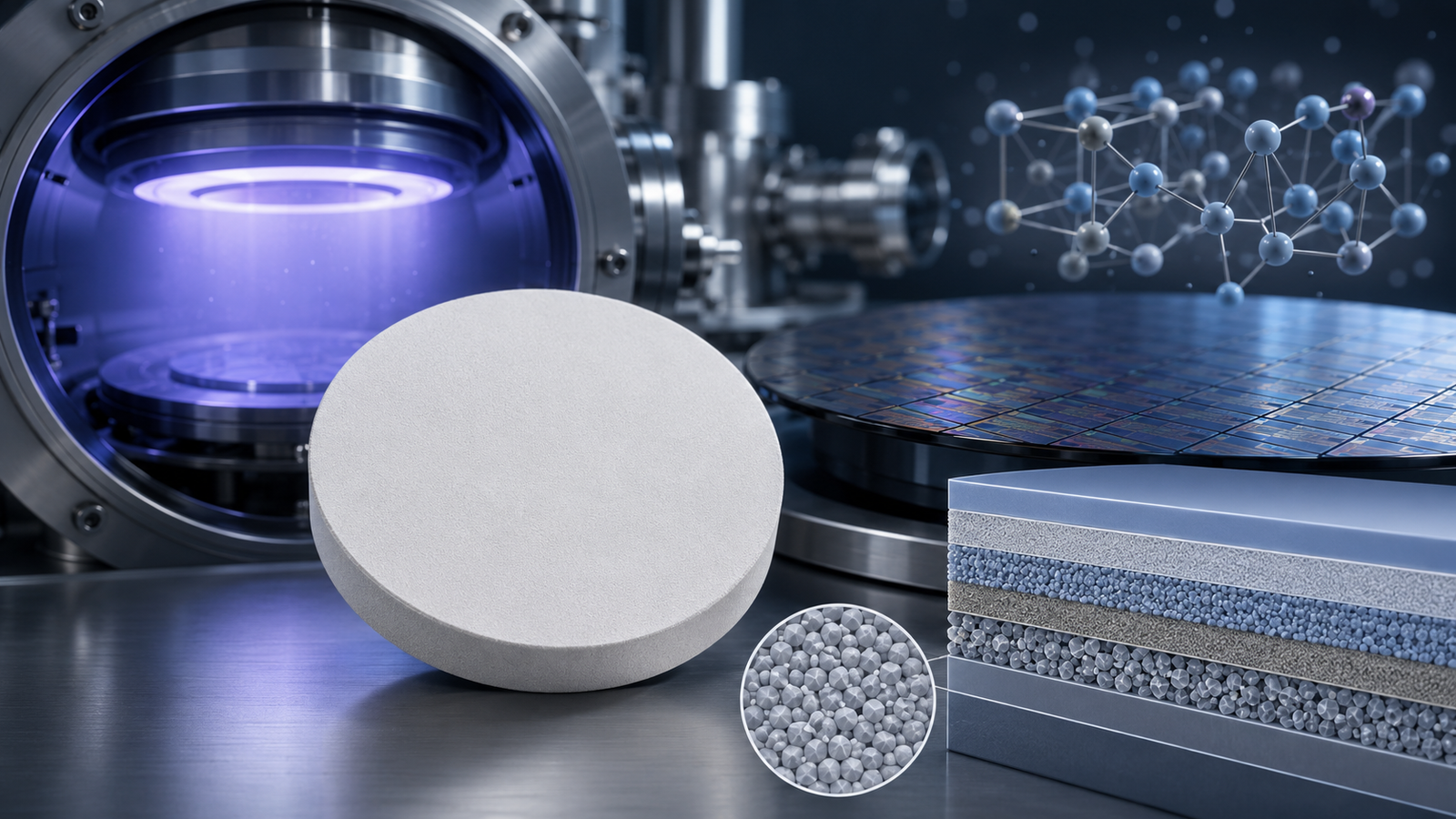
Silicide sputtering targets—especially TaSi₂—are widely used in semiconductor, diffusion barrier, and high-temperature thin-film applications. However, they are also among the most brittle materials used in magnetron sputtering.
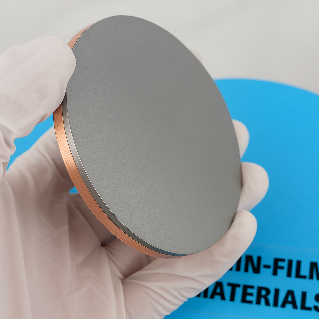
Recently, Thin-Film Materials (TFM) received a real customer case involving a 3-inch TaSi₂ target (99.9%) elastomer-bonded to a 1/8″ Cu backing plate that cracked after the second DC sputtering cycle. The customer provided photos, and the failure pattern revealed important insights into how silicide targets behave under thermal stress.
This article analyzes the case in detail and shares practical lessons to help users avoid similar failures.
1. Background of the Incident
The customer was operating a Kurt J. Lesker DC magnetron sputter system using the following parameters:
- Ramp-up: 10 W/s
- Working power: 200 W
- Ramp-down: 0.5 W/s
- Material: TaSi₂ (tantalum disilicide), 99.9%
- Configuration: Target bonded to copper backing plate + keeper ring
- Failure time: After the second deposition run
Soon after the second deposition, the operator discovered that the target had cracked.
They sent two photos to TFM for assessment:
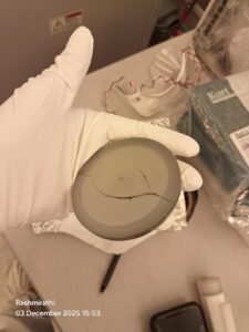
2. What the Photos Tell Us (Field Observation)
2.1 Large radial cracks originating from the center
In the images, the TaSi₂ target shows:
- A primary crack propagating across the diameter
- Secondary cracks branching outward
- A fracture pattern typical of tensile failure in brittle ceramics or intermetallic materials
This is classic “thermal shock cleavage.”
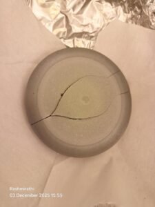
2.2 Crack initiates near the hottest region
The crack starts at the center, which is the region of:
- Highest ion bombardment
- Fastest temperature rise
- Lowest cooling efficiency (compared to edges)
This strongly suggests overheating at the center relative to the outer regions, producing tensile stress that the brittle TaSi₂ cannot withstand.
2.3 No visible chipping or impact marks
The fracture lines are clean and originate internally rather than from a surface chip, which means:
- This is not a handling or transport crack
- The failure occurred during sputtering
The fracture profile is characteristic of thermal expansion mismatch stress between the target and copper plate.
3. Why TaSi₂ Targets Are So Sensitive
Although classified as a “metallic silicide,” TaSi₂ behaves mechanically like a ceramic:
- Very hard
- Very brittle
- Low fracture toughness
- Poor thermal shock resistance
- Strong thermal expansion mismatch with copper
Thermal expansion comparison:
| Material | CTE (×10⁻⁶ / K) |
|---|---|
| TaSi₂ | ~8–9 |
| Cu backing plate | ~16.5 |
When heated, the copper tries to expand almost twice as much as the TaSi₂.
This induces strong tensile stress on the brittle target surface.

4. Power Density Was the Key Factor
A 3″ target has an effective area of ~45.6 cm².
Running at 200 W DC → 4.4 W/cm² power density
For metallic targets, this is mild.
For silicides, a ceramic sputtering target, this is borderline high.
Typical recommended values:
| Target Type | Recommended Power Density |
|---|---|
| Metals | 10–20 W/cm² |
| Ceramic Oxides | 3–6 W/cm² |
| Silicides (TaSi₂, MoSi₂, TiSi₂) | 2–4 W/cm² |
Thus, the customer’s setting (4.4 W/cm²) exceeded the commonly accepted safe range.
The crack’s shape in the customer’s photos exactly matches the stress pattern when the target center overheats relative to the edge.
5. What Likely Happened (TFM Technical Assessment)
Based on the fracture pattern and operating parameters:
5.1 Thermal shock during early cycles
Ceramic-like targets are most vulnerable in the first 1–3 heating/cooling cycles.
The crack appeared during the second run, which fits typical behavior.
5.2 Rapid temperature rise at 200 W
Even with a 10 W/s ramp, the final power is high enough to produce:
- A significant temperature gradient through the TaSi₂
- Tensile stress at the target surface
- Pulling force from the expanding copper plate behind it
This can initiate a full-thickness crack.
5.3 Ignition and stabilization not sufficiently slow
Ceramic targets should follow this sequence:
- Low power ignition (30–80 W)
- Stabilize plasma for 5–10 minutes
- Gradually increase to target power
If power is raised too soon after ignition, the surface experiences shock heating.
5.4 Possible mounting stress
Although the photos don’t show the back, common contributors include:
- Keeper ring tightened too hard
- Uneven mounting pressure
- Partially lifted backing plate
- Minor tilt creating local hot zones
Even small mechanical stresses amplify thermal stress.
6. How to Prevent This in Future
TFM recommends the following best practices for TaSi₂ and other brittle targets:
6.1 Start at lower power
- 30–80 W ignition
- Stabilize for 5–10 minutes
6.2 Gradual ramp-up
Increase power in increments, not all at once.
6.3 Consider a lower maximum power (120–150 W)
Most silicide targets sputter well at lower power while avoiding excessive heating.
6.4 Verify cooling performance
Check:
- Water flow
- Inlet temperature
- No bubbles
- Good contact with cathode plate
6.5 Ensure proper mounting
- Do not overtighten the keeper ring
- Wipe off particles between the backing plate and cathode
- Ensure completely flat, uniform contact
6.6 Condition new targets
Ceramic-type targets always benefit from “gentle first use.”
7. The Critical Role of Pre-Sputtering for Brittle Targets
In addition to ignition and gradual power ramping, one essential step recommended by the TFM technical team and most sputtering system manufacturers is pre-sputtering.
What is pre-sputtering?
Pre-sputtering is a short conditioning process performed before actual deposition.
The shutter remains closed while plasma bombards the target surface at a controlled, moderate power level.
For ceramic-like materials such as TaSi₂, pre-sputtering serves three critical purposes:
- Surface stabilization
It removes loosely bonded surface particles and helps the target reach thermal equilibrium. - Degassing and impurity removal
Any absorbed moisture, oxygen, or trapped gases within the near-surface region are removed gradually, greatly reducing the chance of arc events. - Slow thermal ramping
Instead of jumping directly to full temperature, the target warms up progressively, reducing thermal gradients across the brittle TaSi₂ layer.
Recommended procedure for TaSi₂ from TFM
- Ignition: 30–80 W
- Pre-sputter: 5–10 minutes at 80–120 W (shutter closed)
- Gradual ramp: Increase in small steps (e.g., +20–30 W every few minutes)
- Working power: Only after the target is thermally stable
Why it would have helped in this case
Based on the customer’s photos, the crack pattern clearly indicates that the target experienced:
- A steep temperature gradient
- Rapid stress buildup at the center
- Insufficient surface conditioning
A proper pre-sputtering step would have allowed the TaSi₂ surface to heat uniformly, greatly reducing the likelihood of a large radial fracture during only the second run.
8. Conclusion
This real customer case demonstrates how thermal–mechanical stress can cause a TaSi₂ sputtering target to fracture during early operation.
The failure observed in the photos—large radial cracks originating from the hot center—is typical of ceramic-like sputtering materials subjected to high power density.
With proper ignition, conservative early power settings, and careful mechanical mounting, users can significantly extend the life of silicide sputtering targets.
Thin-Film Materials (TFM) will continue to support customers with technical guidance, material recommendations, and best practices to ensure stable sputtering performance for brittle specialty materials.