Direct answer: dual- and multi-target co-sputtering use two or more independently driven material sources during one deposition. The method can vary the arriving flux from each source, but power settings alone do not guarantee the final film composition, uniformity, adhesion, phase, or device performance. Source material, power mode, individual deposition-rate calibration, cathode geometry, substrate position or motion, pressure, reactive-gas state, re-sputtering, temperature, and post-deposition treatment all have to be controlled and verified on the deposited film.
This guide explains what co-sputtering can control, where its limits are, how to compare it with a pre-alloyed target, and what information to include when requesting sputtering targets for a dual- or multi-source process.
What Is Dual- or Multi-Target Co-Sputtering?
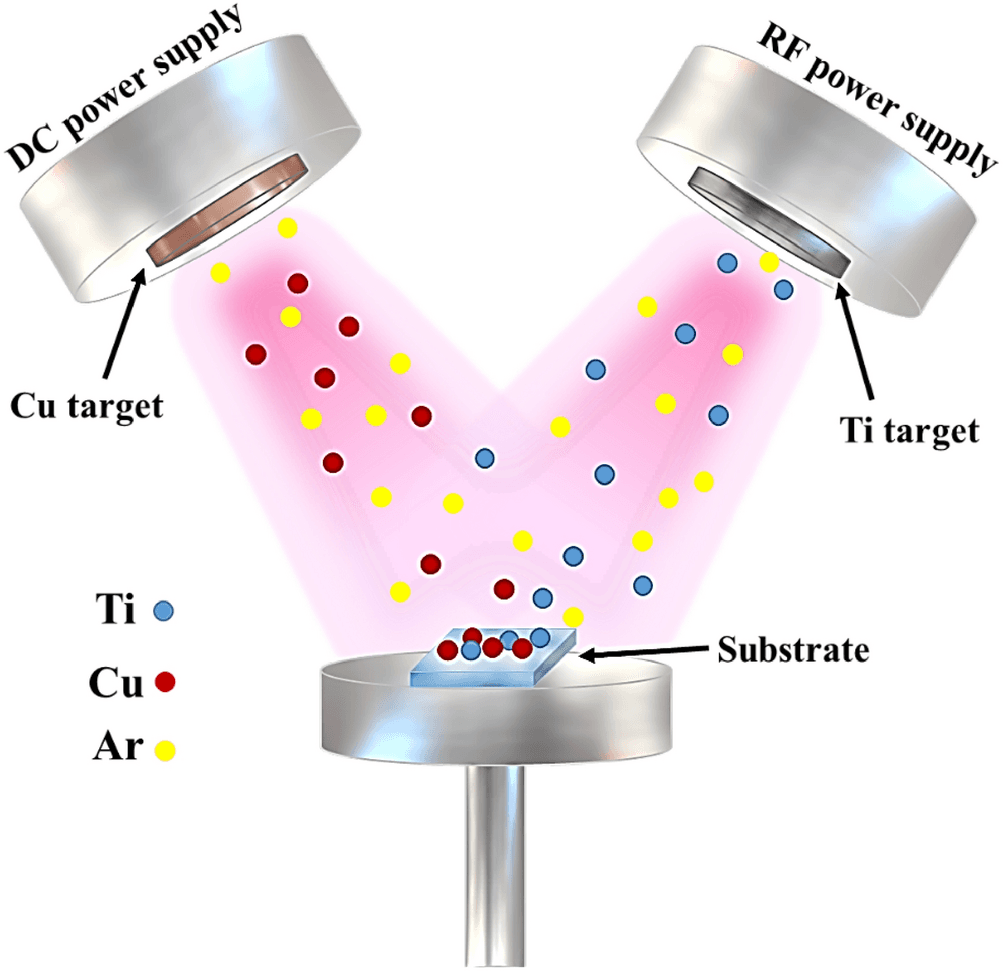
Co-sputtering is simultaneous or intentionally sequenced deposition from two or more sputtering sources onto the same substrate. Each source may use an elemental, alloy, ceramic, or compound target, provided the target, cathode, power supply, and process mode are compatible. Independent source control lets an engineer change the relative material flux without manufacturing a new fixed-composition target for every experiment.
The deposited film is not simply the arithmetic sum of target labels. The contribution from each source depends on its sputter yield, delivered power, erosion state, angular flux distribution, target-to-substrate geometry, gas scattering, and interactions at the growing film. In reactive sputtering, the surface state of each target can also change with reactive-gas partial pressure.
What Co-Sputtering Can—and Cannot—Control
| Question | Co-sputtering provides | It does not guarantee | Verification needed |
|---|---|---|---|
| Film composition | Independent source inputs and a tunable composition window | That power ratio equals atomic ratio | Measure composition on representative positions and runs |
| Spatial grading | Geometry, masks, motion, or programmed source changes can create a gradient | A uniform wafer when flux fields are intentionally non-uniform | Map thickness and composition across the substrate |
| Depth grading | Power or shutter sequences can change the arriving flux with time | The intended phase or complete atomic mixing | Use depth-sensitive composition and structure methods |
| Material discovery | One run can cover multiple compositions in a planned library | That the best library point transfers directly to production | Repeat the selected composition under a controlled process |
| Film performance | A way to explore composition–property relationships | Adhesion, low defect density, conductivity, hardness, or optical performance | Use application-specific film tests |
Why Power Ratio Is Not Film Composition
Independent power is an actuator, not a composition certificate. Published co-sputtering work shows that thickness and composition depend on experimental parameters, system geometry, sputter yield, and the spatial distribution of arriving flux. Other work on multisource deposition starts with single-source rate and composition measurements before calculating a co-deposition condition.
A practical calibration therefore separates three questions:
- What does each source deliver alone? Record the target identity, power mode, delivered power, pressure, gas, source-to-substrate geometry, substrate state, deposition time, and measured thickness or mass gain.
- What changes when sources operate together? Check plasma interaction, pressure control, substrate heating, re-sputtering, source shielding, and whether the combined process changes either source’s stable operating state.
- What reached the film? Measure the deposited composition and thickness at positions relevant to the actual substrate, not only at a single convenient monitor location.
Recalibration may be needed after target replacement, substantial erosion, geometry changes, shield service, or a change in gas or pressure. The required frequency is equipment- and process-specific.
Geometry, Motion, and Composition Uniformity
Confocal sources naturally create different flux distributions across a substrate. That behavior can be useful for a composition-spread library, or undesirable when the objective is a uniform production film. Published combinatorial studies deliberately use target angle, target-to-substrate distance, masks, and power to generate measurable composition gradients.
Substrate rotation can average part of a spatial gradient, but it does not by itself prove uniform thickness or composition. The result also depends on source placement, rotation axis and speed, substrate size, masks, shutters, deposition time, and the angular distribution of each source. A uniformity claim should be supported by a defined map and acceptance criterion.
Reactive Co-Sputtering Adds Another Coupled Variable
When oxygen, nitrogen, or another reactive gas is used, each target may respond differently. Formation of a compound layer on a target can change discharge behavior and sputter yield. Published reactive-sputtering studies show that the transition or poisoning behavior is quantitatively system-dependent, so a gas-flow value from another cathode or chamber is not a transferable recipe.
For a reactive multi-source process, record the gas-control mode and the signal used to identify a repeatable operating state. Useful process evidence may include cathode voltage and current, delivered or reflected RF power, reactive-gas partial pressure, optical-emission or other control signals, deposition rate, and post-run target condition. See the dedicated target poisoning and hysteresis guide for a mechanism-led diagnostic path.
Co-Sputtering or a Pre-Alloyed Target?
| Decision factor | Evaluate co-sputtering when | Evaluate a pre-alloyed or compound target when |
|---|---|---|
| Composition development | Several compositions or gradients must be screened | A fixed, already-qualified source composition is required |
| Equipment | The chamber has compatible sources, controls, space, cooling, and shielding | Only one suitable cathode position is available |
| Process control | Independent rate calibration and film composition mapping are available | Reducing the number of controlled sources is more important |
| Reactive operation | Each source’s reactive state can be monitored and stabilized | Coupled source behavior introduces unacceptable uncertainty |
| Scale-up | Uniformity and repeatability can be demonstrated on the intended substrate and tool | A simpler source architecture is preferred after composition selection |
This is not a universal cost comparison. Target manufacturing, cathode time, calibration runs, chamber maintenance, target utilization, process yield, and changeover requirements can outweigh the purchase price of the source materials.
A Controlled Development Workflow
- Define the film objective. State the required composition range, thickness, spatial or depth profile, substrate, phase or microstructure question, and the actual acceptance tests.
- Confirm equipment compatibility. Record cathode models, target dimensions, backing-plate interfaces, power supplies, cooling, source angles, shutters, substrate motion, and permitted materials.
- Qualify each source separately. Establish a stable operating window and measure single-source deposition rate under the intended geometry and gas conditions.
- Plan the composition matrix. Choose a bounded set of source inputs. Do not assume a linear power-to-composition relationship without measurements.
- Run the combined process. Record delivered power, reflected power where relevant, voltage/current, pressure, gas flows or control signals, substrate motion, time, and source state.
- Map thickness and composition. Use methods appropriate to the elements, expected concentration range, substrate, and required accuracy. Report spatial positions and uncertainty.
- Characterize structure and performance. Composition alone does not establish phase, bonding state, crystallinity, residual stress, adhesion, electrical, optical, magnetic, electrochemical, or mechanical behavior.
- Repeat the selected condition. Demonstrate repeatability before treating a library point as a process specification or scale-up candidate.
What to Include in a Co-Sputtering Target RFQ
- Material and composition required for each target; identify elemental, alloy, ceramic, or compound source.
- Requested purity and the impurities that matter to the application; request real lot data when it is required.
- Target diameter or length, thickness, tolerances, surface finish, edge requirements, and drawing revision.
- Cathode make/model, mounting interface, clamp area, groove or bolt pattern, and any maximum envelope restrictions.
- Bonded or unbonded requirement; backing-plate material, dimensions, reuse status, and proposed bond method if already specified.
- Power mode for each source, intended operating range, cooling arrangement, substrate geometry, and whether reactive gas will be used.
- Expected campaign length, target-change constraints, conditioning limits, and any material-cross-contamination restrictions.
- Required documentation: lot-specific CoA, composition method, dimensional report, SDS scope, packaging, and traceability.
- Whether the goal is a uniform film, a spatial composition spread, a depth gradient, or an alternating multilayer.
For source selection, see the Copper Sputtering Target and Titanium Sputtering Target examples, or send the full source list and cathode drawings through Contact. These product links identify material sources; they do not prescribe a Cu–Ti process or guarantee a particular film composition.
Common Co-Sputtering Mistakes
- Using power percentage as atomic percentage. Calibrate each source and verify the combined film.
- Measuring only the wafer center. Use a map when spatial uniformity or a composition spread matters.
- Changing several variables at once. Preserve a run log that can separate power, gas, pressure, geometry, motion, and temperature effects.
- Ignoring target-life state. Erosion and shield history can change the delivered flux and distribution.
- Assuming co-deposition creates the desired phase. Confirm composition, structure, and any required post-deposition treatment experimentally.
- Comparing unlike evidence. A target CoA describes the source lot; it is not a film-composition or device-performance certificate.
Evidence Boundary
The references below demonstrate co-sputtering methods and dependencies in specific materials, chambers, geometries, power modes, and measurement workflows. They do not establish a universal power ratio, deposition rate, target purity, film composition, scale-up result, or application performance for TFM products. Final process settings and acceptance limits must come from the user’s equipment, film measurements, and qualification plan.
Frequently Asked Questions
Does a 50:50 power split produce a 50:50 atomic-percent film?
Not necessarily. Sputter yield, power mode, source geometry, gas scattering, target condition, re-sputtering, and substrate position can make the film ratio differ from the power ratio. Measure single-source rates and verify the combined film composition.
Can co-sputtering produce a uniform composition?
It can be developed for a defined uniformity target, but uniformity is not automatic. Source placement, flux distribution, substrate motion, masks, pressure, and substrate size must be controlled and the result must be mapped.
When is co-sputtering useful for materials discovery?
It is useful when a planned composition library or gradient can be paired with spatially registered composition, structure, and property measurements. A promising library point still requires repeat deposition and application-specific qualification.
Primary Technical Sources
- Cruz et al., Ion beam analysis and co-sputtering simulation of bi-metal films, Nuclear Instruments and Methods in Physics Research B (2016).
- Gutwirth et al., Tailoring of Multisource Deposition Conditions towards Required Chemical Composition of Thin Films, Nanomaterials (2022).
- Liu et al., Combinatorial development of Zr-Cu-Al-Ag thin film metallic glasses, Scientific Reports (2016).
- Ludwig, Discovery of new materials using combinatorial synthesis and high-throughput characterization, npj Computational Materials (2019).
- Flink et al., Effect of target power density, substrate bias, and temperature on Cr-Al-C film composition, Vacuum (2017).
- Musil et al., Study on reactive sputtering of titanium in a linear magnetron discharge, Surface and Coatings Technology (2006).